Ball pin assembly torsion test marking device and test method

A technology of torque testing and ball pins, which is applied in the field of ball pin assembly torque testing and marking devices, can solve the problems of poor detection accuracy, immature ball pin torque detection technology, low torque detection efficiency, etc., and achieve detection efficiency improvement, fast Easy to read results, easy to read results

Pending Publication Date: 2021-03-19
烟台辰宇汽车部件有限公司
View PDF0 Cites 4 Cited by
  • Summary
  • Abstract
  • Description
  • Claims
  • Application Information

AI Technical Summary

Problems solved by technology

[0003] Aiming at the deficiencies in the prior art, the present invention provides a ball pin assembly torque testing marking device and testing method to solve the problem of immature ball pin torque detection technology and low torque detection efficiency of the ball pin assembly in the prior art And the technical problem of poor detection accuracy

Method used


Image

  • Ball pin assembly torsion test marking device and test method
  • Ball pin assembly torsion test marking device and test method
  • Ball pin assembly torsion test marking device and test method

Examples


Embodiment Construction

[0023] The principles and features of the present invention are described below in conjunction with the accompanying drawings, and the examples given are only used to explain the present invention, and are not intended to limit the scope of the present invention.

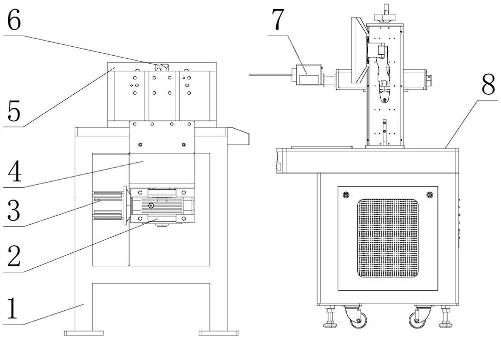
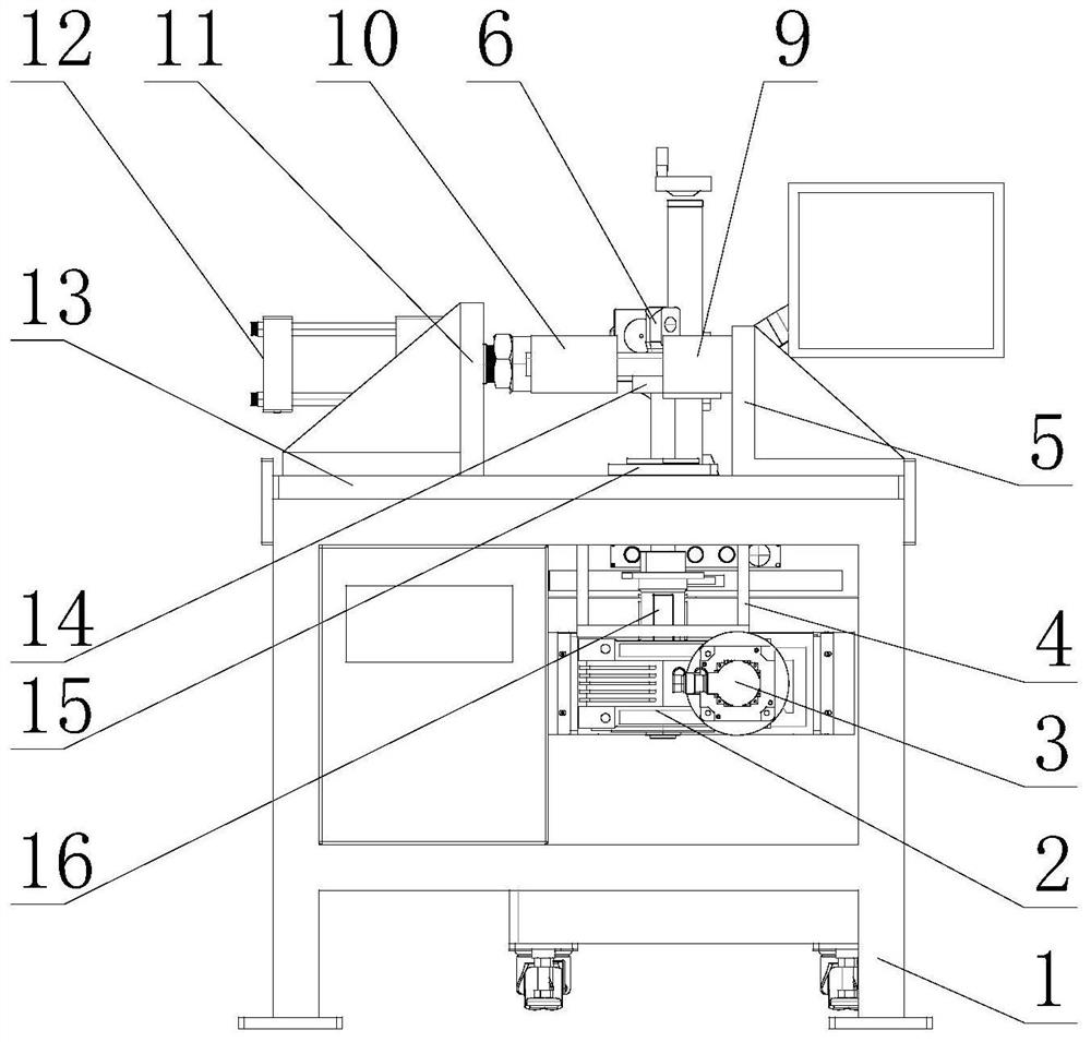
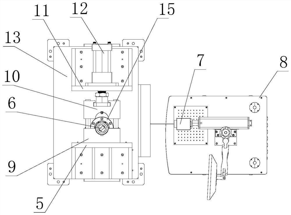
[0024] A ball pin assembly torque testing marking device, the ball pin assembly includes a ball pin 6 and a joint bearing outer casing 14 that is rotatably installed outside the ball pin 6, when the ball pin assembly is installed on the equipment and is in a normal working state, due to excessive There is a pre-tightening force in the installation, and it needs to reach a certain torque value before it can rotate. The target of the test here is the torque value of the rotation of the joint bearing casing 14. The device includes a platform 13, which is installed above the platform 13 and acts on the joint bearing casing 14. The limit pre-tightening mechanism and the power part acting on the ball pin 6 are installed un...


PUM


Abstract

The invention relates to a ball pin assembly torsion test marking device and a test method, and belongs to the technical field of ball pin torsion test. The ball pin assembly torsion test marking device comprises a platform, a limit pre-tightening mechanism which is arranged above the platform and acts on a knuckle bearing sleeve, and a power part which is arranged below the platform and acts on aball pin, the ball pin is connected with the power part through a torque meter. According to the limiting pre-tightening mechanism, the clamping mechanism acts on the knuckle bearing sleeve to simulate the pre-tightening state of the knuckle bearing sleeve during installation, and the technical problems that in the prior art, a ball pin torsion detection technology of a ball pin assembly is immature, the torsion detection efficiency is low, and the detection precision is poor are solved.

Description

technical field [0001] The invention relates to a marking device and a testing method for torsion testing of a ball pin assembly, belonging to the technical field of torsion testing of ball pins. Background technique [0002] The ball pin is a widely used part in the automobile transmission. The parts connected by the ball pin are allowed to have a certain range of torsional swing. The ball pin assembly generally consists of a ball pin and a joint bearing sleeve that is rotatably matched with the ball pin. In the prior art, the ball pin and joint bearing jacket are assembled and then filled with lubricating grease. When the finished product leaves the factory, there are certain requirements for the torque of the ball pin assembly. When the ball pin assembly is installed and used, the torque of the ball pin cannot be too high. Low, if it is too low, the preload effect will not be good, especially not too high, if the torque is higher than 500N, it will easily cause wear and t...

Claims


Application Information

Patent Timeline
Patent Type & Authority Applications(China)
IPC IPC(8): G01L5/00G01B11/27B41J3/407
CPCB41J3/4073G01B11/27G01L5/00
Inventor 傅宇孙立胜高鹏
Owner 烟台辰宇汽车部件有限公司
Why Eureka
Try Eureka