
A safety rope hook state detection device and method

A state detection device and safety rope technology, which is applied in the field of high-altitude work safety, can solve the problems of low efficiency of state detection of safety ropes and hooks, and untimely detection of potential safety hazards, so as to improve accuracy and monitoring efficiency, reduce manpower monitoring, improve The effect of construction safety

Active Publication Date: 2022-02-22
国网山东省电力公司建设公司 +2
View PDF0 Cites 0 Cited by
  • Summary
  • Abstract
  • Description
  • Claims
  • Application Information

AI Technical Summary

Problems solved by technology

[0005] This application provides a safety rope hook state detection device and method to solve the problems in the prior art that the detection efficiency of the safety rope and hook state is low and the hidden dangers are not found in time

Method used


Image

  • A safety rope hook state detection device and method
  • A safety rope hook state detection device and method
  • A safety rope hook state detection device and method

Examples


Embodiment 1

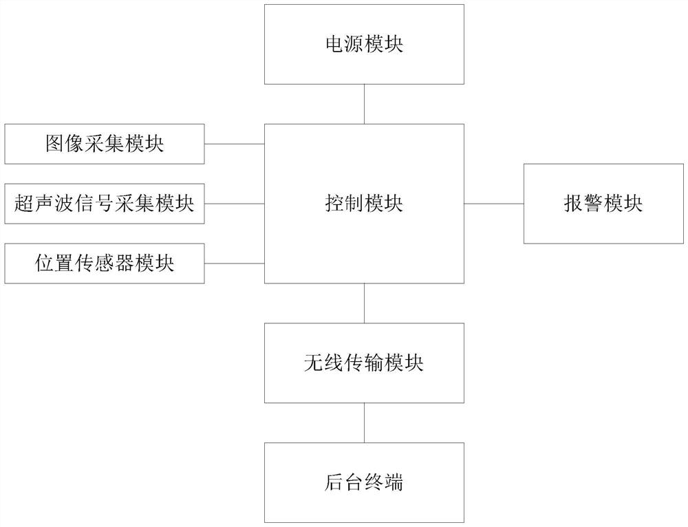
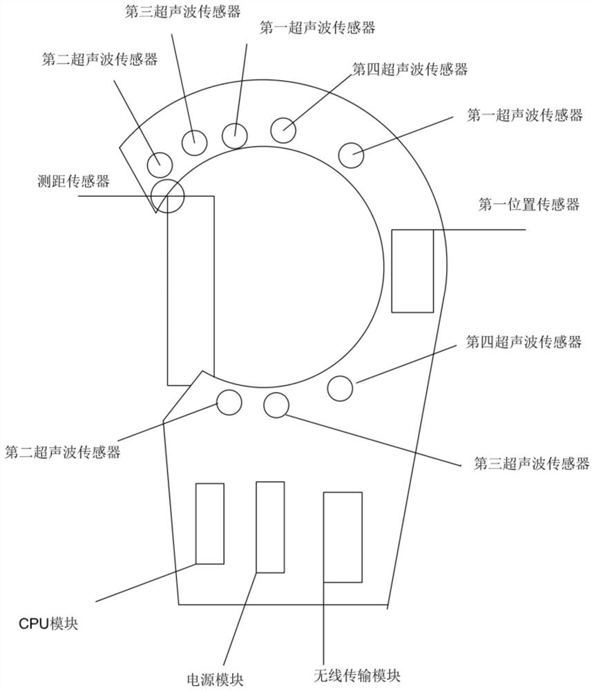
[0045] see figure 1 , figure 1 This is a structural block diagram of a safety rope hook state detection device provided in an embodiment of the present application. Depend on figure 1It can be seen that this embodiment provides a safety rope hook state detection device, which mainly includes: a control module, an image acquisition module, an ultrasonic signal acquisition module, a position sensor module, a wireless transmission module, a background terminal, a power supply module and an alarm module. Among them, the control module is respectively connected with the image acquisition module, the ultrasonic signal acquisition module, the position sensor module, the power supply module and the alarm module, and the control module is also connected with the background terminal through the wireless transmission module; the image acquisition module is used to collect the construction site safety rope hook Image data, and analyze and process the image data; ultrasonic signal acquis...

Embodiment 2

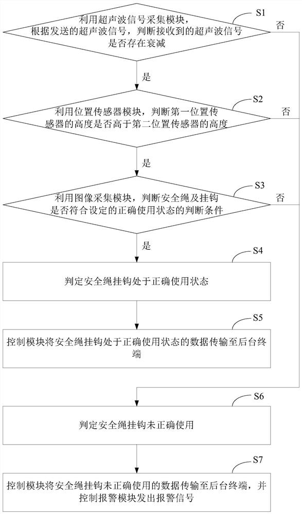
[0053] exist figure 1 and figure 2 On the basis of the embodiment shown, see image 3 , image 3 A schematic flowchart of a method for detecting a state of a safety rope hook provided by an embodiment of the present application. Depend on image 3 It can be seen that the method for detecting the state of the safety rope hook in this embodiment includes the following processes:

[0054] S1: Use the ultrasonic signal acquisition module to determine whether the received ultrasonic signal is attenuated according to the transmitted ultrasonic signal.

[0055] S2: Use the position sensor module to determine whether the height of the first position sensor is higher than the height of the second position sensor.

[0056] S3: Using the image acquisition module, it is judged whether the safety rope and the hook meet the set judgment conditions of the correct use state.

[0057] When the received ultrasonic signal is attenuated, the height of the first position sensor is higher th...


PUM


Abstract

The application discloses a device and method for detecting the state of a safety rope hook. The device includes: a control module, an image acquisition module, an ultrasonic signal acquisition module, a position sensor module, a wireless transmission module, a background terminal, a power supply module and an alarm module, and a control module They are respectively connected with each module, and also connected with the background terminal through the wireless transmission module. The method includes: judging whether the received ultrasonic signal is attenuated according to the sent ultrasonic signal; judging whether the height of the first position sensor is higher than the height of the second position sensor; judging whether the safety rope and the hook meet the set correct use state Judgment conditions; if yes, determine that the safety rope hook is in the correct use state; otherwise, determine that the safety rope hook is not used correctly; transmit the data that the safety rope hook is not used correctly to the background terminal, and send an alarm signal. Through the application, the detection efficiency can be effectively improved, and potential safety hazards can be found in time.

Description

technical field [0001] The present application relates to the technical field of high-altitude work safety, and in particular, to a device and method for detecting the state of a safety rope hook. Background technique [0002] Safety is an important issue in working at height environments. Taking the construction of substations as an example, the construction of substations involves a lot of content, and the height of various structures is high, which belongs to high-altitude operations and requires the use of seat belts. In order to ensure the standard use of the seat belt by the staff and the personal safety of the staff, it is necessary to timely detect the status of the safety rope and hook. [0003] At present, the method of detecting the state of the safety rope and the hook is usually manual monitoring, that is, the state of the safety rope and the hook is checked one by one manually at regular intervals. [0004] However, the current method of detecting the state o...

Claims


Application Information

Patent Timeline
Patent Type & Authority Patents(China)
IPC IPC(8): G05B19/048G01D21/02G08B21/18G08C17/02G08C23/02H04N7/18
CPCG05B19/048G01D21/02G08C23/02G08C17/02H04N7/185G08B21/18
Inventor 张斌罗荣钧何勇军程剑郑磊孙晓迪尹习伟滕飞孙文义于润华李然侯炜
Owner 国网山东省电力公司建设公司
Learn More