A fast tinning device for transformer
A transformer and fast technology, applied in the manufacture of inductors/transformers/magnets, auxiliary devices, welding equipment, etc., can solve the problems of inability to improve the quality of transformers, low work efficiency, and inaccurate tinning.
- Summary
- Abstract
- Description
- Claims
- Application Information
AI Technical Summary
Problems solved by technology
Method used
Image
Examples
Embodiment 1
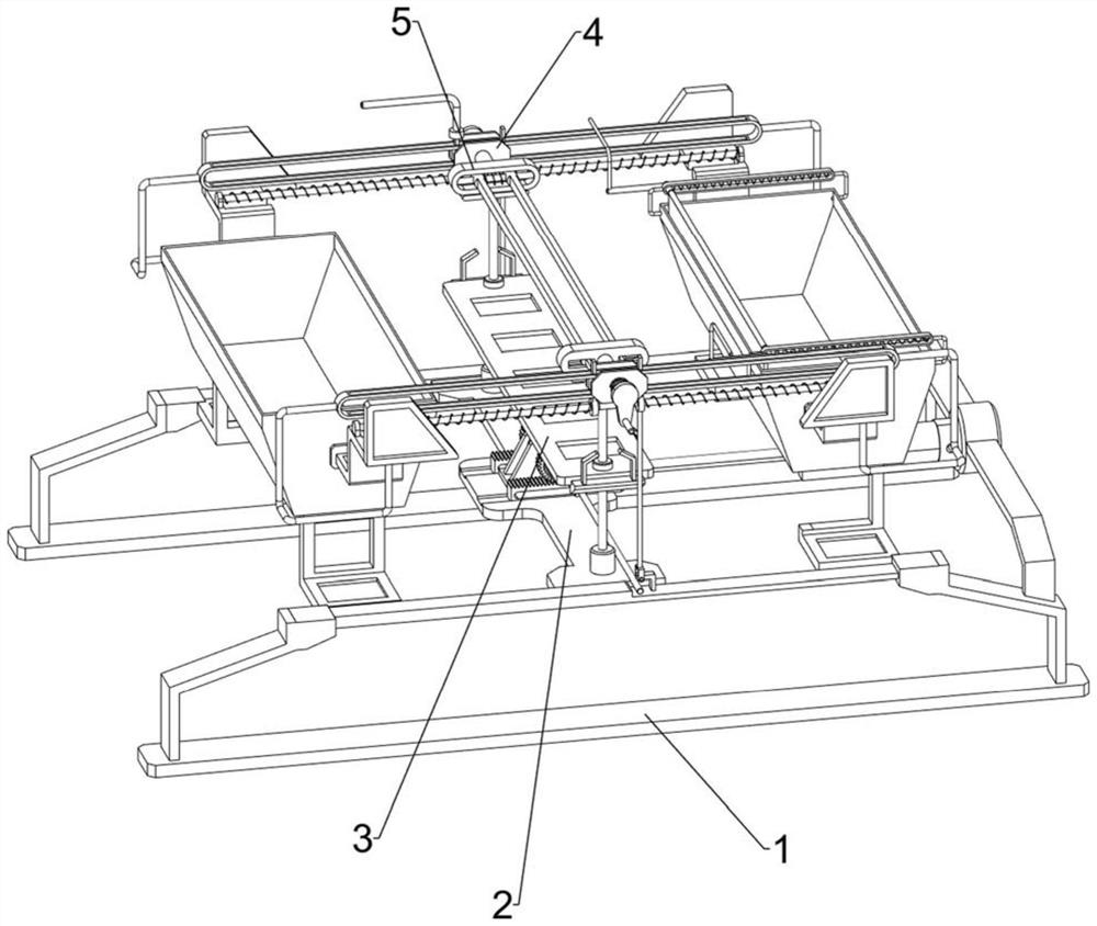
[0028] Such as figure 1 As shown, a transformer rapid tinning device includes a bottom plate 1, a first bracket 2, a lifting mechanism 3, a moving mechanism 4 and a turning mechanism 5. The bottom plate 1 is provided with a first bracket 2, and the middle part of the first bracket 2 is provided with a The lifting mechanism 3 is provided with a moving mechanism 4 on the first bracket 2, and a turning mechanism 5 is arranged on the moving mechanism 4, and the moving mechanism 4 cooperates with the turning mechanism 5.
[0029] When the transformer needs to be tinned, the staff first pours a certain amount of tin and clear water into the moving mechanism 4 respectively, then the staff places the transformer on the lifting mechanism 3, and then the staff starts the lifting mechanism 3, and the lifting mechanism 3 moves upwards Move, when moving to a certain position, the staff pulls the overturning mechanism 5 backwards, then the overturning mechanism 5 resets and clamps the trans...
Embodiment 2
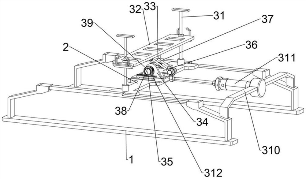
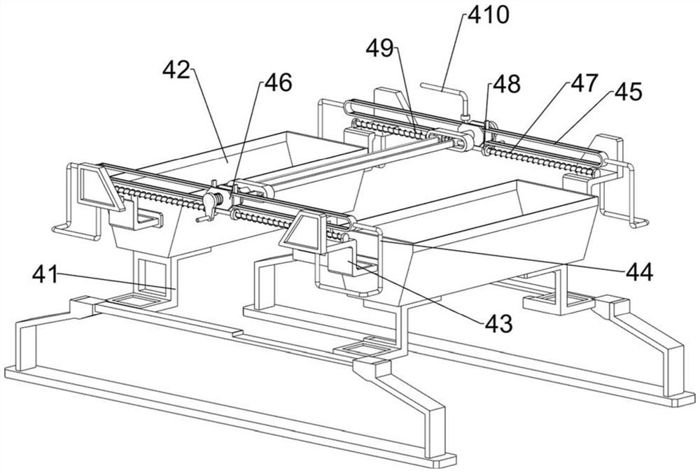
[0031] Such as figure 2 , image 3 and Figure 4As shown, on the basis of Embodiment 1, the lifting mechanism 3 includes a first guide rod 31, a slide plate 32, a first bearing seat 33, a second bearing seat 34, a first rotating shaft 35, a first connecting rod 36, a first Two connecting rods 37, one-way bearing 38, gear 39, second support 310, cylinder 311 and rack 312, the first guide rod 31 is arranged on the front and rear sides of the middle part of the first support 2, between the two first guide rods 31 The sliding type is provided with a slide plate 32, the bottom of the slide plate 32 is provided with a first bearing seat 33, the first bracket 2 between the two first guide rods 31 is provided with a second bearing seat 34 symmetrically front and back, and the two second bearing seats 34 is rotatably provided with a first rotating shaft 35, the first rotating shaft 35 is provided with a first connecting rod 36, the first bearing seat 33 is provided with two second c...
Embodiment 3
[0038] Such as Figure 5 , Figure 6 and Figure 7 As shown, the fourth fixed block 6, the fifth fixed block 7 and the wedge plate 8 are also included, the fourth fixed block 6 is provided at the front and rear ends of the two clamping blocks 54, and the fifth fixed block is provided at the front and rear sides of the slide plate 32. Block 7, wedge-shaped plates 8 are symmetrically arranged on the two fifth fixed blocks 7 left and right.
[0039] Sliding plate 32 upwards drives wedge-shaped plate 8 to contact with the fourth fixed block 6, and extrudes the fourth fixed block 6, and the fourth fixed block 6 moves back and drives clamp block 54 to slide back on the third guide rod 53, and the second The elastic member 55 is stretched, the slide plate 32 slides downwards to drive the wedge-shaped plate 8 out of contact with the fourth fixed block 6, the second elastic member 55 resets and drives the clamping block 54 to slide toward each other on the third guide rod 53, and the...
PUM
 Abstract
Description
Claims
Application Information
 - R&D
- Intellectual Property
- Life Sciences
- Materials
- Tech Scout
- Unparalleled Data Quality
- Higher Quality Content
- 60% Fewer Hallucinations
Browse by: Latest US Patents, China's latest patents, Technical Efficacy Thesaurus, Application Domain, Technology Topic, Popular Technical Reports.
© 2025 PatSnap. All rights reserved.Legal|Privacy policy|Modern Slavery Act Transparency Statement|Sitemap|About US| Contact US: help@patsnap.com


