Eureka AIR delivers breakthrough ideas for toughest innovation challenges, trusted by R&D personnel around the world.

Dual-output driving motor for vehicle

A driving motor, dual output technology, applied in the direction of electrical components, electromechanical devices, electric components, etc., can solve the problems of high vibration and noise, adsorption to the stator, easy deflection, etc., to achieve low vibration and noise, ensure normal operation, shaft Good for moderate effect

Pending Publication Date: 2021-03-19
SUZHOU LVKON TRANSMISSION TECH CO LTD
View PDF0 Cites 0 Cited by
  • Summary
  • Abstract
  • Description
  • Claims
  • Application Information

AI Technical Summary

Problems solved by technology

At present, there are two main structures of dual-output motors: (1) There is a partition in the middle of the casing, and the two rotors are supported by two bearings. This structure has good reliability, but the partition increases the axial length, and for different lengths Stator and rotor, the generality of the casing is very poor; (2) There is no partition in the middle of the casing, and a single bearing is nested between the motor shafts of the two rotors. This structure saves axial length, simple structure, and low cost, but for The rotor with strong magnetic force tends to be deflected or even adsorbed to the stator in the middle, resulting in loud vibration and noise or even unable to rotate normally

Method used


Image

  • Dual-output driving motor for vehicle
  • Dual-output driving motor for vehicle

Examples


specific Embodiment 1

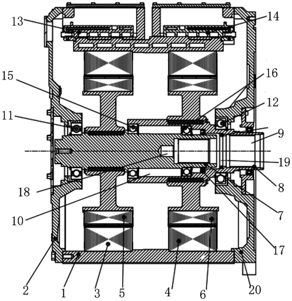
[0026] Specific embodiment one, see figure 1 When the front end cover 2 is specifically a closed end cover, the whole structure is used as a pure electric system to drive the motor.

specific Embodiment 2

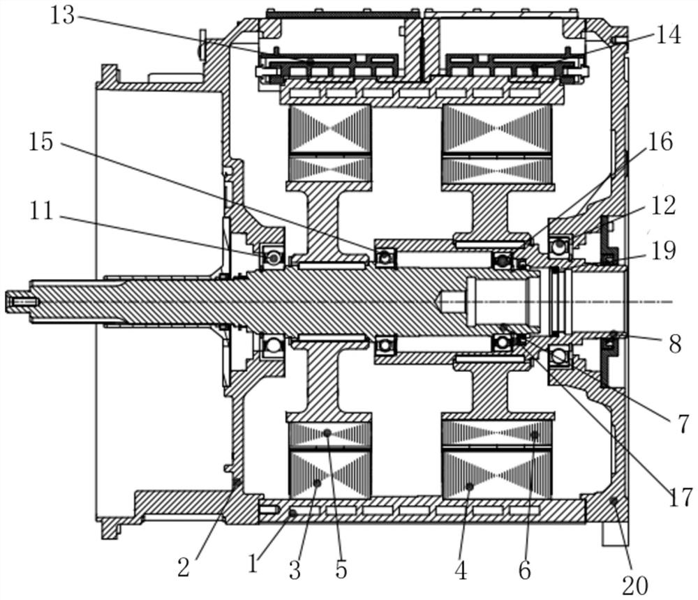
[0027] Specific embodiment two, see figure 2 The structure of the front end cover 2 is specifically in the form of a clutch housing, the first motor shaft protrudes from the end cover, and is used for connecting with a matching engine to form a hybrid power system.

[0028] Its working principle is as follows: the first stator and the second stator share the casing, and they are arranged side by side coaxially along the axial direction; there is no partition between the two stators, and a normal electrical gap is maintained. The second motor shaft is a hollow shaft. The first motor shaft passes through it; in the axial middle of the housing, at least two support bearings are nested between the second motor collar wall and the outer ring surface of the first motor shaft, and the two bearings at the axial start and end There is a large distance between the two support bearings to ensure stable and reliable support. There is no direct rigid connection between the first motor sha...


PUM


Abstract

The invention provides a dual-output driving motor for a vehicle, and the two motor shafts are of a structure with double bearings nested in the middle, thereby enabling the axial centering degree tobe good, and guaranteeing the vibration noise. A first stator and a second stator are fixedly arranged in an inner cavity of the machine shell in the axial direction in sequence, the first stator andthe second stator are arranged at intervals in the axial direction, no partition plate exists, a first rotor is arranged in the center of the first stator, a second rotor is arranged in the center area of the second stator, and the first rotor is fixedly arranged in the corresponding axial area of the first motor shaft in a sleeving mode. The second motor shaft is a hollow shaft, a penetrating hollow cavity is formed in the center of the second motor shaft, the output end of the first motor shaft is arranged in the penetrating hollow cavity in a centering mode, and at least two supporting bearings are arranged in a gap ring space formed by axial overlapping axial areas of the second motor shaft and the first motor shaft. The inner ring of the supporting bearing is sleeved at the corresponding shaft end of the first motor shaft, and the outer ring of the supporting bearing is arranged close to the inner wall of the corresponding shaft end of the second motor shaft.

Description

technical field [0001] The invention relates to the technical field of drive motor structure, in particular to a dual output vehicle drive motor. Background technique [0002] For a hybrid or pure electric vehicle equipped with an AMT gearbox, there is a problem of power interruption during the gear shifting process. There will be a sense of frustration when the vehicle is running, the gear shifting noise is loud, and it is easy to cause the vehicle to slip when climbing a slope and cannot shift gears. The dual-output motor and dual-input gearbox can well solve the problem of interruption of shifting power. At present, there are two main structures of dual-output motors: (1) There is a partition in the middle of the casing, and the two rotors are supported by two bearings. This structure has good reliability, but the partition increases the axial length, and for different lengths Stator and rotor, the generality of the casing is very poor; (2) There is no partition in the m...

Claims


Application Information

Patent Timeline
Patent Type & Authority Applications(China)
IPC IPC(8): H02K16/00H02K5/22H02K5/124H02K5/16
CPCH02K5/124H02K5/161H02K5/225H02K16/00
Inventor 李磊何韬吕小科王艳坤
Owner SUZHOU LVKON TRANSMISSION TECH CO LTD
Why Eureka
Eureka Blog
Learn More