Novel bone lengthening intramedullary nail
A technique of intramedullary nailing and bone lengthening, applied in the field of new bone lengthening intramedullary nails, can solve the problems of inability to drive, stress shielding, stress stimulation, etc., and achieve the effect of long time with frame, convenient operation and easy fixation
- Summary
- Abstract
- Description
- Claims
- Application Information
AI Technical Summary
Problems solved by technology
Method used
Image
Examples
Embodiment 1
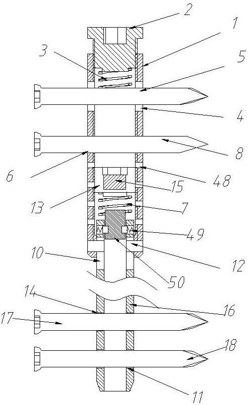
[0036] Embodiment one, such as figure 1 As shown, a new bone extension intramedullary nail includes a main nail of the intramedullary nail. The main nail of the intramedullary nail is composed of an upper nail body 1 and a lower nail body 16, and the upper nail body 1 and the lower nail body 16 are both hollow structure, and connected by the connecting pin 12, the lower tube wall of the upper nail body 1 is provided with a scale hole 48, and the upper part of the lower nail body 16 is axially provided with a long sliding groove 10, and the connecting pin 12 can slide along the long groove 10 Slide up and down, the diameter of the upper nail body 1 is larger than the diameter of the lower nail body 16, and an extension device is installed in the cavity formed between the upper nail body 1 and the lower nail body 16, and the extension device includes a static bone Between the screw 8 and the lower nail body 16, the adjustment screw sleeve 13, the spring 27, the spring base 50 th...
Embodiment 2
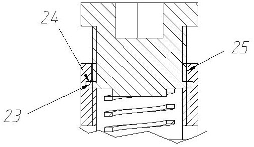
[0039] Embodiment two, such as figure 2 As shown, the difference between the present embodiment and the first embodiment is the connection mode between the tail cap 2 and the upper nail body 1: the inner wall of the upper nail body 1 is provided with an annular groove 24 and a vertical guide groove 25 communicated with the annular groove 24. A protrusion 23 is provided on the tail cap 2 , and the protrusion 23 can rotate along the annular groove 24 and slide vertically along the vertical guide groove 25 . When adjusting the tail cap 2, make the projection 23 vertically slide along the vertical guide groove 25, and when sliding to the annular groove 24, rotate the tail cap 2 to fix the tail cap 2 in the annular groove 24.
Embodiment 3
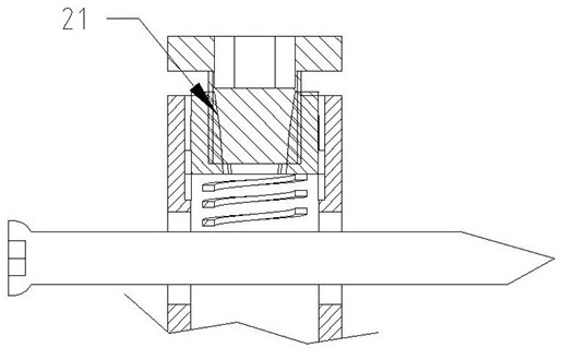
[0040] Embodiment three, such as image 3 As shown, the difference between the present embodiment and the first embodiment is the connection mode between the tail cap 2 and the upper nail body 1: in the present embodiment, the head of the tail cap 2 is provided with an expansion sleeve 29, which can be screwed into the tail cap 2 to The expansion sleeve 29 is fixed on the inner wall of the upper nail body 1 .
PUM
 Abstract
Description
Claims
Application Information
 - R&D
- Intellectual Property
- Life Sciences
- Materials
- Tech Scout
- Unparalleled Data Quality
- Higher Quality Content
- 60% Fewer Hallucinations
Browse by: Latest US Patents, China's latest patents, Technical Efficacy Thesaurus, Application Domain, Technology Topic, Popular Technical Reports.
© 2025 PatSnap. All rights reserved.Legal|Privacy policy|Modern Slavery Act Transparency Statement|Sitemap|About US| Contact US: help@patsnap.com


