Transfer printing equipment of bandages

A bandage and equipment technology, applied in the field of bandage transfer printing equipment, can solve the problems of low processing efficiency and inability to form continuous processing equipment, so as to improve processing efficiency and realize the effect of mechanical automatic processing

Inactive Publication Date: 2021-03-23
RES INST OF ZHEJIANG UNIV TAIZHOU
View PDF10 Cites 0 Cited by
  • Summary
  • Abstract
  • Description
  • Claims
  • Application Information

AI Technical Summary

Problems solved by technology

[0002] For the transfer printing of bandages, in the prior art, manual loading and paper tearing are performed and semi-automatic hot pressing equipment is used for transfer printing processing, which cannot form continuous forming processing equipment, resulting in low processing efficiency

Method used


Image

  • Transfer printing equipment of bandages
  • Transfer printing equipment of bandages
  • Transfer printing equipment of bandages

Examples


Embodiment Construction

[0025] Below in conjunction with accompanying drawing and specific embodiment the present invention will be described in further detail:

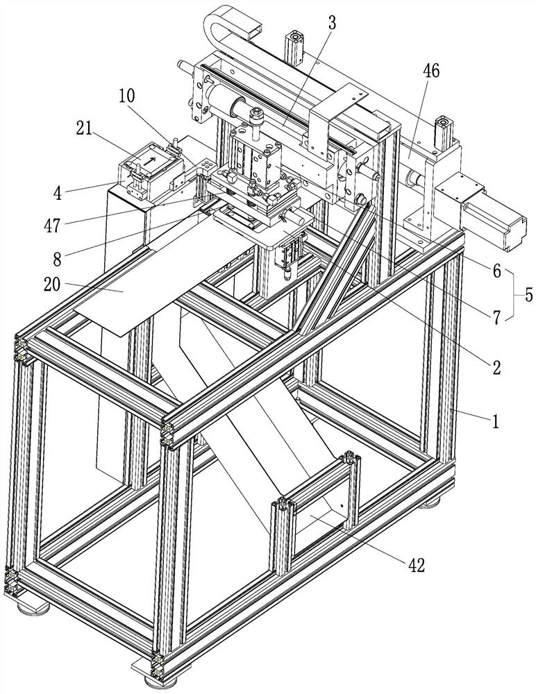
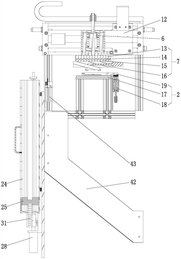
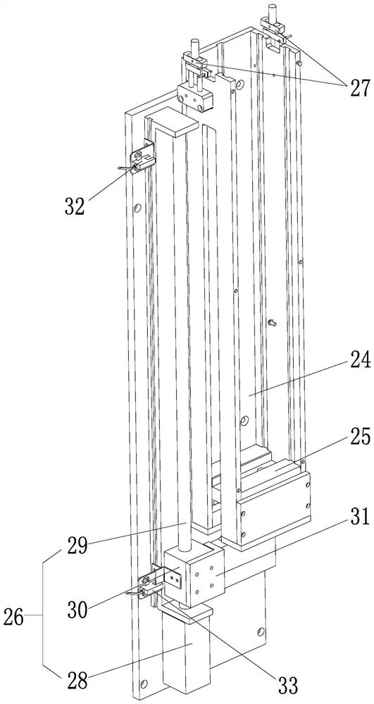
[0026] see Figure 1 to Figure 9 , the present invention provides a bandage transfer device, including a frame 1, a feeding mechanism 46 arranged on the frame 1, a paper tearing mechanism 2, a translation mechanism 3, and a paper tearing mechanism 2 connected to the translation mechanism 3. The transfer device 5 that reciprocates between the transfer paper feeding device 4, the transfer device 5 includes a transfer cylinder 6, a transfer head 7 connected to the stroke rod of the transfer cylinder 6, and the translation mechanism 3 There are also several suction rods 8 connected to it, and the suction rods 8 are inserted in the stepped holes 9 of the transfer head 7, and the center line of the stepped holes 9 is collinear with the moving direction of the transfer head 7, so that the transfer The head 7 moves up and down along the center lin...


PUM


Abstract

The invention discloses transfer printing equipment of bandages. The transfer printing equipment comprises a machine frame, a feeding mechanism, a paper tearing mechanism, a translation mechanism anda transfer printing device, wherein the feeding mechanism is arranged on the machine frame; the transfer printing device is connected to the translation mechanism to do reciprocating motion between the paper tearing mechanism and a transfer printing paper charging device; the transfer printing device comprises a transfer printing air cylinder and a transfer printing head which is connected to a stroke rod of a transfer printing cylinder; a plurality of sucking rods are also connected to the translation mechanism and are inserted in step holes of the transfer printing head; and the central lines of the step holes and the motion direction of the transfer printing head are collinear, and thus, the transfer printing head is moved up and down relative to the sucking rods along the central linesof the step holes; and sucking heads of the sucking rods are located in the step holes or outside the step holes. According to the transfer printing equipment disclosed by the invention, automatic machining of transfer printing of the bandages is realized, and thus, the machining efficiency is greatly improved.

Description

technical field [0001] The invention belongs to the technical field of special equipment, and in particular relates to a bandage transfer printing equipment. Background technique [0002] For the transfer printing of bandages, in the prior art, manual loading and paper tearing are performed and semi-automatic hot pressing equipment is used for transfer printing processing, which cannot form continuous forming processing equipment, resulting in low processing efficiency. Contents of the invention [0003] Therefore, the main purpose of the present invention is to solve the above problems and provide a bandage transfer printing device. [0004] In order to achieve the above objectives, the technical solution adopted by the present invention is to provide a bandage transfer printing equipment, including a frame, a feeding mechanism arranged on the frame, a paper tearing mechanism, a translation mechanism, and a tear-off A transfer device that reciprocates between the paper m...

Claims


Application Information

Patent Timeline
Patent Type & Authority Applications(China)
IPC IPC(8): B41F16/02
CPCB41F16/02
Inventor 王维镝李广平林国飞杨莉莉王维锐
Owner RES INST OF ZHEJIANG UNIV TAIZHOU
Why Eureka
Try Eureka