
Metal pipe fitting end machining device

A technology for metal pipe fittings and processing devices, applied in the field of metal pipe fitting end processing devices, can solve the problems of difficulty in control, large human factors, and large flying chips.

Active Publication Date: 2021-04-06
沧州东海电力管件有限公司
View PDF8 Cites 0 Cited by
  • Summary
  • Abstract
  • Description
  • Claims
  • Application Information

AI Technical Summary

Problems solved by technology

[0002] At present, the processing of metal pipe fittings is widely used in all walks of life, and for the end processing of metal pipe fittings, especially for the processing of grinding, drilling and sealing of the end of metal pipe fittings, the main production method is to manually clamp the metal pipe fittings , and then artificially use grinding machines, drilling equipment, and lathes to process the corresponding ports. This port processing method has the following defects: (1) Processing a metal pipe requires a lot of labor, uses many processing equipment, and has a long production cycle. The production efficiency is low and the production cost is high; (2) The influence of human factors is large. Due to the uneven technical level, proficiency and working attitude of each operator, the quality of the processed metal pipe fittings is unstable and difficult to control; (3) A large number of flying chips are generated during port processing, which can easily have a great impact on the health of the operator; (4) Due to the processing restrictions of various processing equipment and the limitation of manual operation, it is often only possible to carry out the corresponding length The processing of metal pipe fittings, the processing of pipe fittings is greatly affected by restrictions

Method used


Image

  • Metal pipe fitting end machining device
  • Metal pipe fitting end machining device
  • Metal pipe fitting end machining device

Examples


Embodiment 1

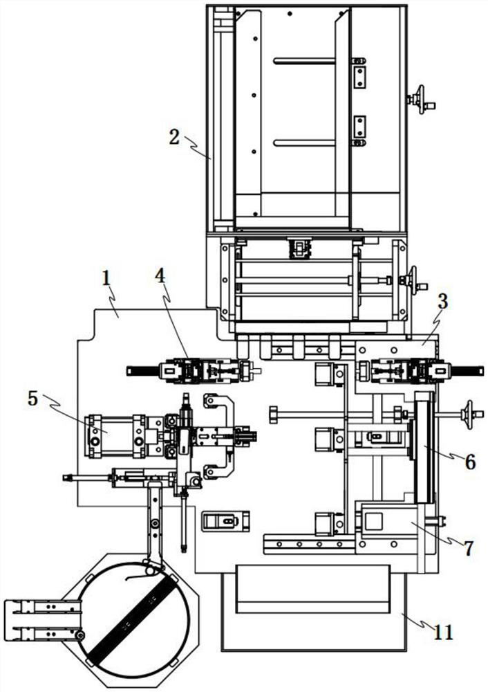
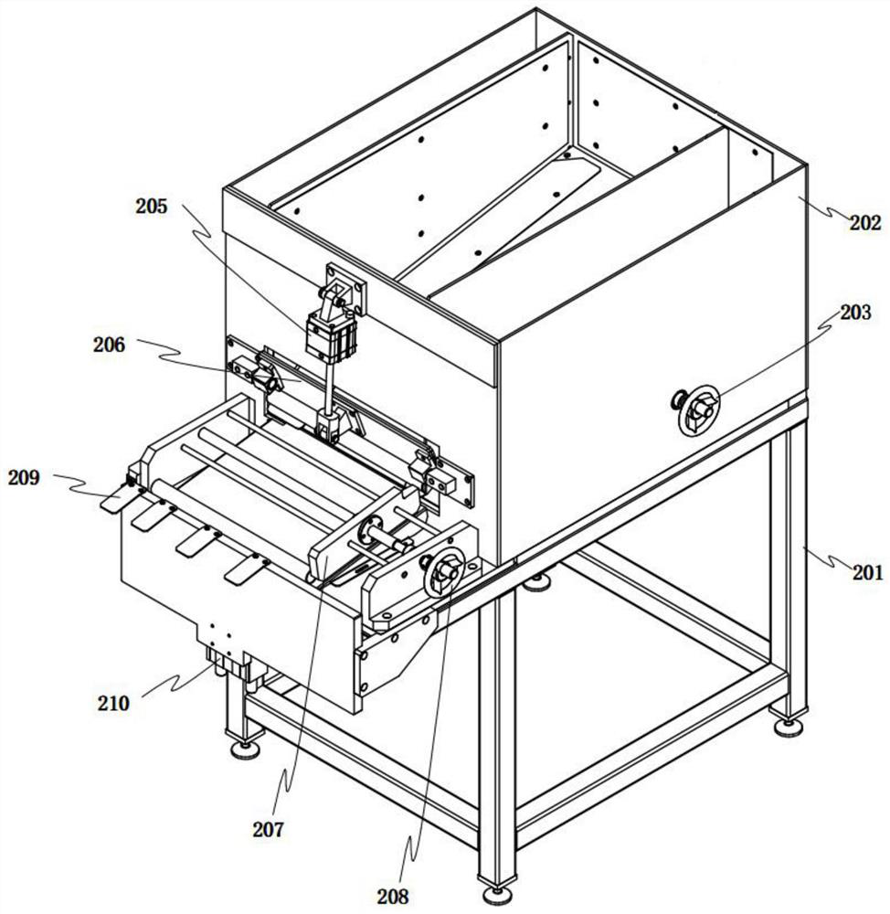
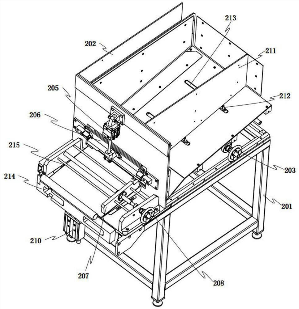
[0038] When the processing device was working, the opening and closing cylinder 205 of the metal pipe fitting storage input mechanism 2 first drove the opening and closing door 206 to open the front side frame opening of the storage frame 202, so that the metal pipe fittings stored in the storage frame 202 were released from the frame under the action of gravity. The mouth rolls down to the output port of the mechanism chassis 201, and then the ejection block 214 is driven by the ejection cylinder 210 to lift the metal pipe on the output port, and rolls out along the export tongue plate 209 to the pipe processing support seat I8, Among them, the movable side frame edge 211 in the pipe storage frame 11 can be adjusted by the adjustment wheel lever I 203 to slide along the guide chute 213, thereby changing the size of the space in the storage frame 202 to adapt to the storage of metal pipes of different lengths. The movable frame edge 207 on one side of the head can be driven by ...


PUM


Abstract

The invention relates to a metal pipe fitting end machining device. The device comprises a machining table body, a metal pipe fitting storage and input mechanism is arranged at the end of one side of the machining table body, a pipe fitting storage frame is arranged on the other side of the machining table body, and a pipe fitting machining supporting base I, a pipe fitting machining supporting base II and a pipe fitting machining supporting base III are sequentially arranged on a table top of the machining table body. A pipe orifice grinding mechanism is arranged on the side edge portion of the pipe fitting machining supporting base I, a pipe orifice blocking mechanism is arranged on the side edge portion of the pipe fitting machining supporting base II, and an end drilling mechanism fixed to a position adjusting mechanism is arranged on the side edge portion of the pipe fitting machining supporting base III. According to the device, mechanical and automatic machining of metal pipe fitting port inner and outer pipe wall face grinding, port drilling and pipe orifice blocking is achieved, meanwhile, the machining device can be adjusted according to the lengths of pipe fittings so as to meet the machining requirements of pipe fittings with different lengths, the pipe fitting machining efficiency is improved, the labor and equipment investment cost is reduced, and the influence of human factors is reduced.

Description

technical field [0001] The invention relates to the technical field of metal pipe fitting processing equipment, in particular to a metal pipe end processing device. Background technique [0002] At present, the processing of metal pipe fittings is widely used in all walks of life, and for the end processing of metal pipe fittings, especially for the processing of grinding, drilling and sealing of the end of metal pipe fittings, the main production method is to manually clamp the metal pipe fittings , and then artificially use grinding machines, drilling equipment, and lathes to process the corresponding ports. This port processing method has the following defects: (1) Processing a metal pipe requires a lot of labor, uses many processing equipment, and has a long production cycle. The production efficiency is low and the production cost is high; (2) The influence of human factors is large. Due to the uneven technical level, proficiency and working attitude of each operator, t...

Claims


Application Information

Patent Timeline
IPC IPC(8): B23P23/04
CPCB23P23/04
Inventor 王毅军
Owner 沧州东海电力管件有限公司
Learn More