Optical system design method based on combination of TIR and micro-lens array

A microlens array and optical system technology, applied in optics, optical components, instruments, etc., can solve the problems of few microlens arrays and lack of complete design of free-form surface microlenses.

Pending Publication Date: 2021-03-23
EAST CHINA JIAOTONG UNIVERSITY
View PDF8 Cites 1 Cited by
  • Summary
  • Abstract
  • Description
  • Claims
  • Application Information

AI Technical Summary

Problems solved by technology

However, there are relatively few studies on the application of microlens arrays in LED light sources, and most of the re

Method used


Image

  • Optical system design method based on combination of TIR and micro-lens array
  • Optical system design method based on combination of TIR and micro-lens array
  • Optical system design method based on combination of TIR and micro-lens array

Examples


Embodiment Construction

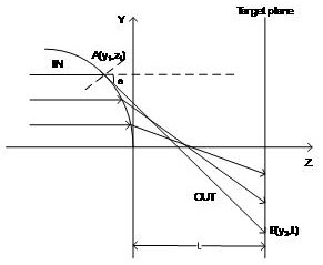
[0046] The specific implementation of the present invention will be described in detail below in conjunction with the accompanying drawings. Such as figure 1 As shown, the specific situation of the optical path of the free-form surface microlens of the present invention is introduced. When the light emitted from the LED light source passes through the TIR lens, all the light becomes parallel to the optical axis, and the parallel light will be redistributed through the microlens array again, and finally evenly distributed on the target plane. The shape of the free-form surface microlens is determined by the following scheme:

[0047] In this embodiment, a Cartesian coordinate system is established based on the cross-section passing through the central axis of rotation of the free-form surface microlens as the reference plane. The central axis of rotation is the Z axis, and the direction passing through the origin of the coordinate system and perpendicular to the central axis i...


PUM


Abstract

The invention provides an LED high-uniformity and high-efficiency optical system design method based on combination of a TIR and a micro lens array. The micro-lens array not only has the optical performance of a traditional lens, but also has many special optical performances, and is widely applied to LED light sources in recent years. However, most research pays attention to the manufacturing process, and a complete mathematical model for designing and establishing a free-form surface is lacked. Therefore, a set of complete free-form surface micro-lens mathematical model is established according to the TIR characteristics and the refraction law. And a group of differential equations are solved through numerical values to obtain the contour of the free-form surface micro lens. And finally,the micro-lens array is simulated by using ray tracing software Trace Pro under the conditions of a near field and a far field respectively, and the influence of the characteristics of the micro-lensarray on the illumination performance is discusssed. Results show that the smaller the radius of the micro lens is, the better the illumination effect is, the uniformity and efficiency of the micro lens can reach over 90%, and the prospect of the micro lens array in practical application can be effectively broadened.

Description

technical field [0001] The invention belongs to the field of optical technology and lighting technology, and in particular relates to a free-form surface of a microlens used for redistributing energy of an LED light source to realize uniform lighting and high efficiency. Background technique [0002] As the fourth-generation lighting source, light-emitting diodes (LEDs) have many advantages such as small size, fast response, long life, and no pollution. With the continuous improvement of LED light efficiency, LEDs are widely used in indoor lighting and outdoor lighting also increasingly widespread. However, since the spatial light intensity of LEDs approximates the Lambertian cosine distribution, directly using LEDs for lighting without secondary light distribution will form a circular spot with a bright center and gradually darkening surroundings on the target surface, with poor uniformity and large It is difficult for light to irradiate the target surface with a small fie...

Claims


Application Information

Patent Timeline
IPC IPC(8): G02B27/00
CPCG02B27/0012
Inventor 祝振敏姚佩琦张福民汪志钰
Owner EAST CHINA JIAOTONG UNIVERSITY
Why Eureka
Try Eureka