High-temperature alloy complex thin-walled workpiece casting system

A pouring system and high-temperature alloy technology, applied in the field of alloy investment casting, can solve the problems of difficult casting process, difficult forming of thin-walled parts, large alloy paste area, etc. Good effect, the effect of improving casting qualification rate

Active Publication Date: 2021-03-26
SHENYANG LIMING AERO-ENGINE GROUP CORPORATION
View PDF7 Cites 2 Cited by
  • Summary
  • Abstract
  • Description
  • Claims
  • Application Information

AI Technical Summary

Problems solved by technology

However, due to the characteristics of the alloy, such as large mushy area, high liquid viscosity, and serious loosening tendency, it is especially used in the production of thin-walled parts. During the casting process, thin-walled parts are difficult to form (under-cast), easy to loosen and crack, and the casting process is difficult. great

Method used


Image

  • High-temperature alloy complex thin-walled workpiece casting system
  • High-temperature alloy complex thin-walled workpiece casting system
  • High-temperature alloy complex thin-walled workpiece casting system

Examples


Embodiment 1

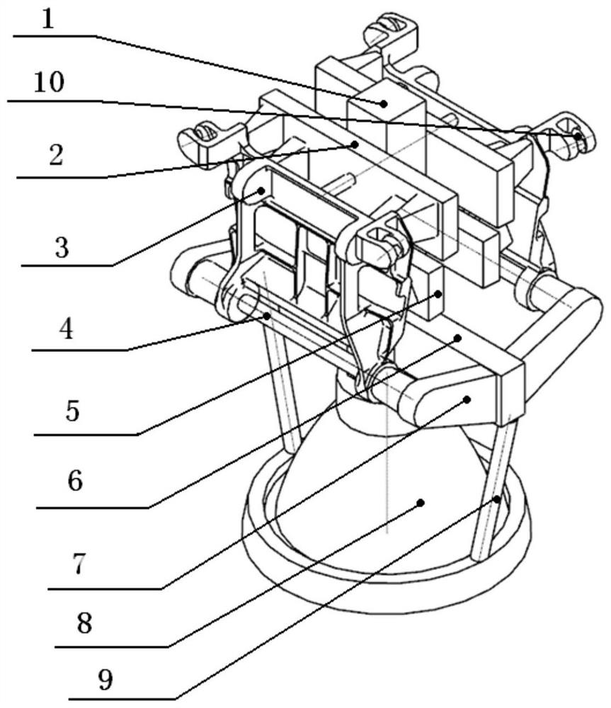
[0031] like figure 2 As shown, a high-temperature alloy complex thin-walled gating system, the gating system is a set of two-piece mold:

[0032] The pouring system is provided with a basic pouring unit, a sprue cup 8 and an exhaust channel 9, and the basic pouring unit is composed of a sprue 1, a runner A2, a runner B5, a runner C6, a runner D7, Composed of anti-deformation rod M4 and anti-deformation rod N10, the specific structure of the gating system is as follows:

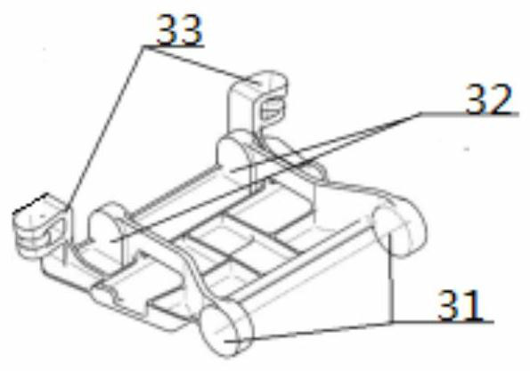
[0033] The basic pouring unit structure is that two runners C6 are symmetrically arranged on the left and right sides of the bottom of the sprue 1, and two runners B5 and two runners A2 are symmetrically arranged on the front and rear sides of the sprue 1 in sequence, and The runner A2 is located below the runner B5, a pair of runners D7 are arranged symmetrically at the outer ends of the front and rear sides of the runner C6, and the anti-deformation rod M4 is arranged between the two front pin hole seats 3...

Embodiment 2

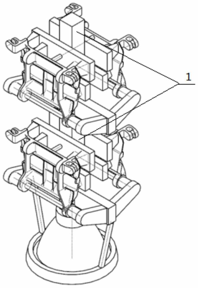
[0044] like image 3 As shown, a high-temperature alloy complex thin-walled gating system, the gating system is a set of four-piece mold:

[0045] The pouring system is provided with two basic pouring units, a sprue cup 8 and an exhaust channel 9. The basic pouring unit consists of a sprue 1, a runner A2, a runner B5, a runner C6, and a runner D7, anti-deformation rod M4, anti-deformation rod N10, the specific structure of the pouring system is as follows:

[0046] The basic pouring unit structure is that two runners C6 are symmetrically arranged on the left and right sides of the bottom of the sprue 1, and two runners B5 and two runners A2 are symmetrically arranged on the front and rear sides of the sprue 1 in sequence, and The runner A2 is located below the runner B5, a pair of runners D7 are arranged symmetrically at the outer ends of the front and rear sides of the runner C6, and the anti-deformation rod M4 is arranged between the two front pin hole seats 31 of the wax m...


PUM

PropertyMeasurementUnit
Diameteraaaaaaaaaa
Diameteraaaaaaaaaa
Diameteraaaaaaaaaa

Abstract

The invention relates to the field of alloy investment casting, in particular to a high-temperature alloy complex thin-walled workpiece casting system which is characterized in that two cross gates Care symmetrically arranged on the left and right sides of the top of a sprue, two cross gates B and two cross gates A are symmetrically arranged on the front and back sides of the sprue successively,the cross gates A are located below the cross gates B, a pair of cross gates D is symmetrically arranged on the front and back side of the cross gates C, an anti-deformation rod M is arranged betweentwo front pin hole seats of a casting wax mould, and an anti-deformation rod N is arranged in a rotating pin hole seat of the device in the casting wax mould. When the casting wax mould is pressed, via the mould, the anti-deformation rod M, the anti-deformation rod N and the casting wax mould are formed integrally. A sprue cup communicates with the sprue of a basic casting unit directly, and two exhaust passages are arranged symmetrically and communicates with the cross gates C and the sprue cup. The risk of defects such as deformation, looseness, cracks and the like can be reduced effectively, and the casting percent of pass of casting products is improved.

Description

technical field [0001] The invention relates to the field of alloy investment casting, in particular to a pouring system for complex thin-wall parts of high-temperature alloys. Background technique [0002] JG4246A alloy has a series of advantages such as light specific gravity, high high temperature strength, excellent oxidation resistance and high temperature structure stability, so it can well meet the special needs of high temperature bearing and ablation resistance of a certain type of thin-walled parts of the third and fourth generation machines. However, due to the characteristics of the alloy, such as large mushy area, high liquid viscosity, and serious loosening tendency, it is especially used in the production of thin-walled parts. During the casting process, thin-walled parts are difficult to form (under-cast), easy to loosen and crack, and the casting process is difficult. great. The casting involved in the present invention has many reinforcing ribs, and the wa...

Claims


Application Information

Patent Timeline
IPC IPC(8): B22C9/08B22C7/02B22C9/04B22C9/20B22C9/22
CPCB22C9/082B22C9/088B22C7/02B22C9/20B22C9/22B22C9/04
Inventor 孙长波王健楠吴晓娟尚伟周君华
Owner SHENYANG LIMING AERO-ENGINE GROUP CORPORATION
Why Eureka
Try Eureka