Inflation amount control method and system

A control method and a technology for air charge, applied in the field of air charge control method and system, can solve problems such as excessively rich mixture, true reflection of air charge, adverse effects on motor vehicle running smoothness, etc., and achieve the effect of improving running smoothness

Pending Publication Date: 2021-03-26
SAIC MOTOR
View PDF4 Cites 2 Cited by
  • Summary
  • Abstract
  • Description
  • Claims
  • Application Information

AI Technical Summary

Problems solved by technology

In a dynamic situation (that is, when the pedaling depth of the accelerator pedal is constantly changing), there may be a large gap between the pressure change in the intake pipe and the air charge in the engine cylinder, so that the change in the air charge measured in the intake system cannot truly reflect the cylinder. Changes in the amount of air in the
[0003] In addition, since the naturally aspirated engine needs to inject fuel before the intake valve opens to fully atomize the fuel, there is a dead time between the intake air volume used to calculate the fuel injection volume and the actual intake air volume when the intake valve is closed ( Refers to the time when the inflation gas arrives in the engine cylinder from the measurement position of the inflation amount of the intake system) is an objective existence, and the inflation amount before the intake valve when the intake valve is closed cannot be truly reflected by the measured inflation amount
This makes it possible that there may be a large deviation between the air charge used to calculate the fuel injection amount and the actual air charge in the cylinder, so that the fuel injection amount calculated by the engine based on the air charge that has a large deviation from the actual charge amount, There is a large deviation from the actual required fuel injection quantity, which makes the mixture in the cylinder too rich or too lean, which will have a negative impact on the smoothness of the motor vehicle.

Method used


Image

  • Inflation amount control method and system
  • Inflation amount control method and system
  • Inflation amount control method and system

Examples


Embodiment Construction

[0045] The following will clearly and completely describe the technical solutions in the embodiments of the application with reference to the drawings in the embodiments of the application. Apparently, the described embodiments are only some of the embodiments of the application, not all of them. Based on the embodiments in this application, all other embodiments obtained by persons of ordinary skill in the art without making creative efforts belong to the scope of protection of this application.

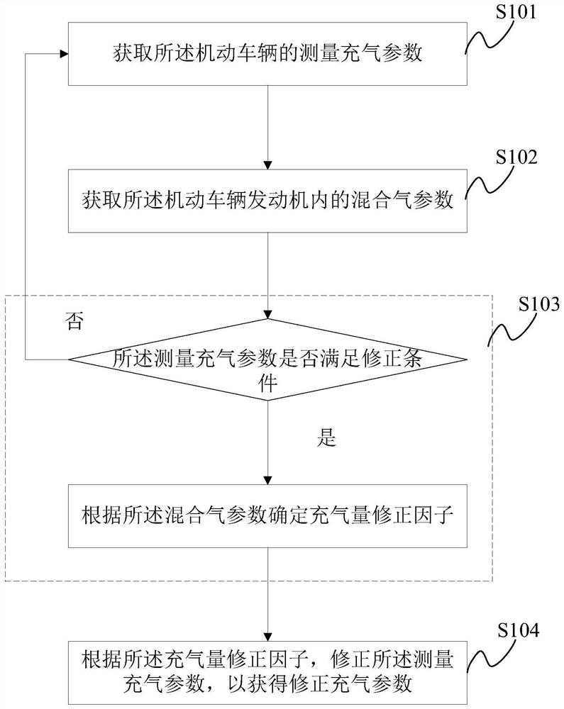
[0046] The embodiment of the present application provides a method for controlling the amount of inflation, such as figure 1 As shown, applied to a motor vehicle, the control method of the inflation amount includes:

[0047] S101: Obtain the measured inflation parameters of the motor vehicle;

[0048] S102: Obtain the gas mixture parameters in the motor vehicle engine;

[0049] S103: Judging whether the measured inflation parameters meet the correction conditions, if yes, determin...


PUM


Abstract

The invention discloses an inflation amount control method and system. According to the inflation amount control method, an inflation amount correction factor is determined according to obtained mixedgas parameters after obtaining measurement inflation parameters of a motor vehicle and judging that the measurement inflation parameters meet a correction condition, the measurement inflation parameters are corrected by using the inflation amount correction factor, and corrected inflation parameters are obtained, so that the inflation amount of the motor vehicle calculated according to the corrected inflation parameters is close to the actual air inflow in an engine, and the purpose that the corrected inflation parameters are closer to the actual air inflow of the engine is achieved. The situation that mixed gas in an air cylinder is too thick or too thin due to the fact that the oil injection amount calculated by the engine according to the inflation amount with the large deviation fromthe actual inflation amount has the large deviation from the actually-needed oil injection amount is avoided, and the running smoothness of the motor vehicle is improved.

Description

technical field [0001] The present application relates to the technical field of vehicle engineering, and more specifically, to a method and system for controlling the amount of air to be charged. Background technique [0002] During the engine calibration process of a motor vehicle, the charge amount (or air intake amount) is an important parameter affecting the fuel injection amount of the engine. In a dynamic situation (that is, when the pedaling depth of the accelerator pedal is constantly changing), there may be a large gap between the pressure change in the intake pipe and the air charge in the engine cylinder, so that the change in the air charge measured in the intake system cannot truly reflect the cylinder. Changes in the amount of air in the interior. [0003] In addition, since the naturally aspirated engine needs to inject fuel before the intake valve opens to fully atomize the fuel, there is a dead time between the intake air volume used to calculate the fuel ...

Claims


Application Information

Patent Timeline
Patent Type & Authority Applications(China)
IPC IPC(8): F02D41/14F02D41/18
CPCF02D41/0002F02D41/1486F02D41/18
Inventor 仇杰薛小兵虞金霞殷俊姚若禹李继徐佳孙健赵森
Owner SAIC MOTOR
Why Eureka
Try Eureka