Transfer device

A transfer device and driving device technology, applied in the direction of conveyor, transportation and packaging, non-mechanical conveyor, etc., can solve the problem of high cost of conveying elements and achieve the effect of small wear phenomenon

Inactive Publication Date: 2016-04-06
ROBERT BOSCH GMBH
View PDF7 Cites 4 Cited by
  • Summary
  • Abstract
  • Description
  • Claims
  • Application Information

AI Technical Summary

Problems solved by technology

However, articulated conveying elements are relatively expensive and costly to manufacture

Method used


Image

  • Transfer device
  • Transfer device
  • Transfer device

Examples


Embodiment Construction

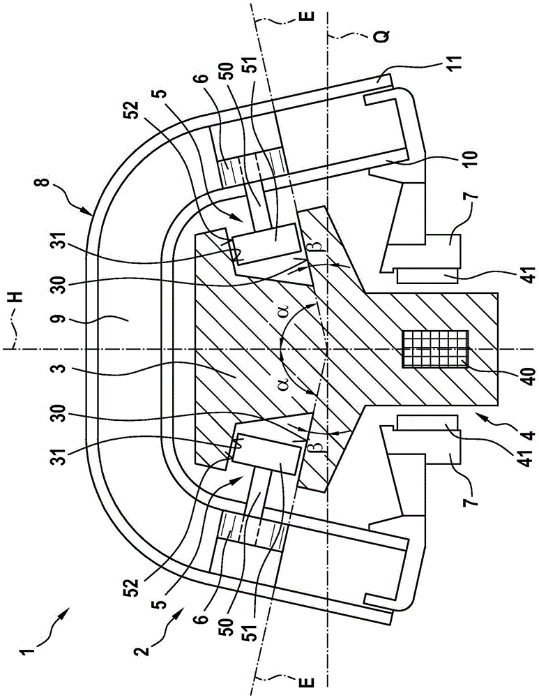
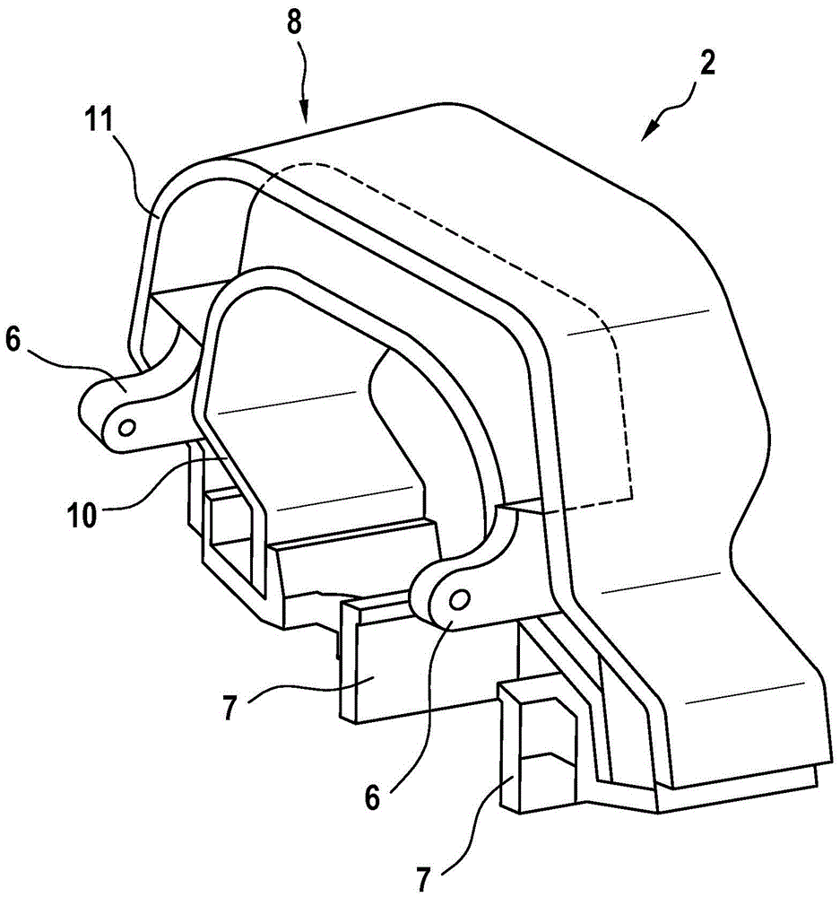
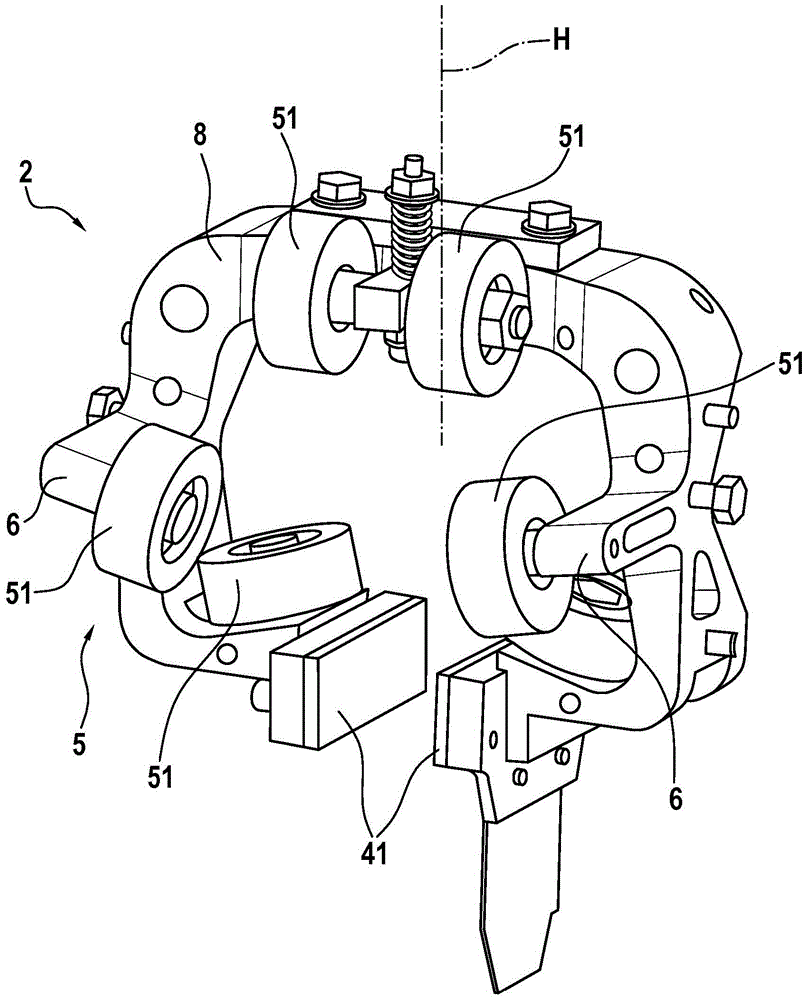
[0022] Refer to the following figure 1 and 2 A transfer device 1 according to a preferred embodiment of the present invention will be described in detail.

[0023] as from figure 1 As can be seen in the figure, the transfer device 1 according to the invention comprises at least one movable element 2 which is movable on a movement track 3 . The movement path 3 can be a circumferentially closed movement path or alternatively also a linear movement path. Preferably, a plurality of movable elements 2 , which can each be controlled individually, are arranged on the movement track 3 . Transfer devices of this type are used, for example, when feeding products to and / or transporting products from machines, especially packaging machines.

[0024] Furthermore, the transfer device 1 comprises a linear motor drive 4 comprising a coil 40 integrated into the stationary movement path 3 and a permanent magnet 41 , wherein the permanent magnet 41 is arranged on the movable element 2 .

[...


PUM


Abstract

The invention relates to a transfer device comprising a moveable element (2), a stationary guide rail (3), and a linear motor drive device (4) for driving the moveable element (2).Said moveable element (2) comprises support elements (5) which can be brought into contact with the guide rail (3), and at least one of the support elements has a contact area which is arranged at an angle (a) not equal to 90 DEG to a vertical axis (H) of the moveable element (2) and at an angle (beta) not equal to 90 DEG to a transverse axis (Q) of the moveable element (2).

Description

technical field [0001] The invention relates to a transfer device, in particular for conveying products, for example to a packaging machine. Background technique [0002] Transfer systems of different configurations are known. For example, DE 10 2011 003 178 A1 discloses a transfer system in which a movable conveying element can be moved on a stationary, circumferential movement path by means of a linear motor drive. In principle, such a device has proven to be effective, however, slippage can occur between the movable conveyor element and the moving track when driving in curves. In particular, increased wear on the conveying elements and / or the moving rails can also occur when driving in curves. Furthermore, a transport device is known from DE 10 2010 027 925 A1, which has an articulated conveying element. With the aid of the articulated conveying element, problems which arise especially when driving in curves can be solved. However, articulated conveying elements are r...

Claims


Application Information

Patent Timeline
Patent Type & Authority Applications(China)
IPC IPC(8): B65G54/02
CPCB65G54/02
Inventor P·卡松J·温德斯海默B·维尔克M·哈尼施S·格兰P·M·冯埃伦施泰因
Owner ROBERT BOSCH GMBH
Why Eureka
Try Eureka