Exhaust oil separation structure, compressor and air conditioner

A compressor and oil separation technology, which is applied to machines/engines, mechanical equipment, liquid fuel engines, etc., can solve the problems of reduced space utilization, large space occupation, and increased compressor size, so as to reduce volume and improve oil and gas separation. The effect of efficiency and separation effects

Pending Publication Date: 2021-03-26
ZHUHAI GREE REFRIGERATION TECH CENT OF ENERGY SAVING & ENVIRONMENTAL PROTECTION
View PDF1 Cites 4 Cited by
  • Summary
  • Abstract
  • Description
  • Claims
  • Application Information

AI Technical Summary

Problems solved by technology

However, this type of oil separator is installed outside the compressor, which increases the size of the compressor, takes up a lot of space, and reduces space utilization

Method used


Image

  • Exhaust oil separation structure, compressor and air conditioner
  • Exhaust oil separation structure, compressor and air conditioner
  • Exhaust oil separation structure, compressor and air conditioner

Examples


Embodiment Construction

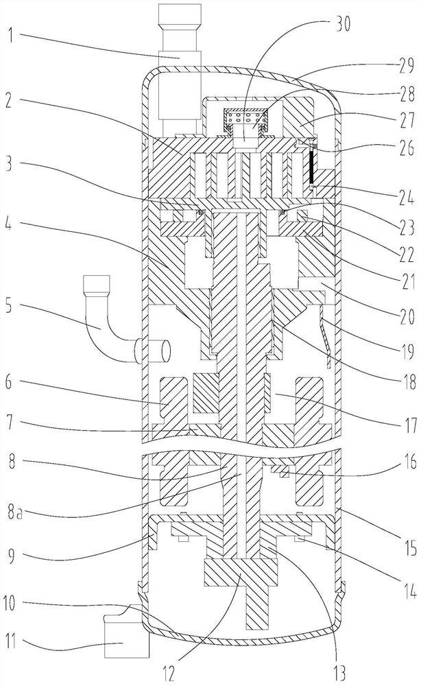
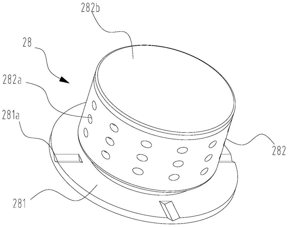
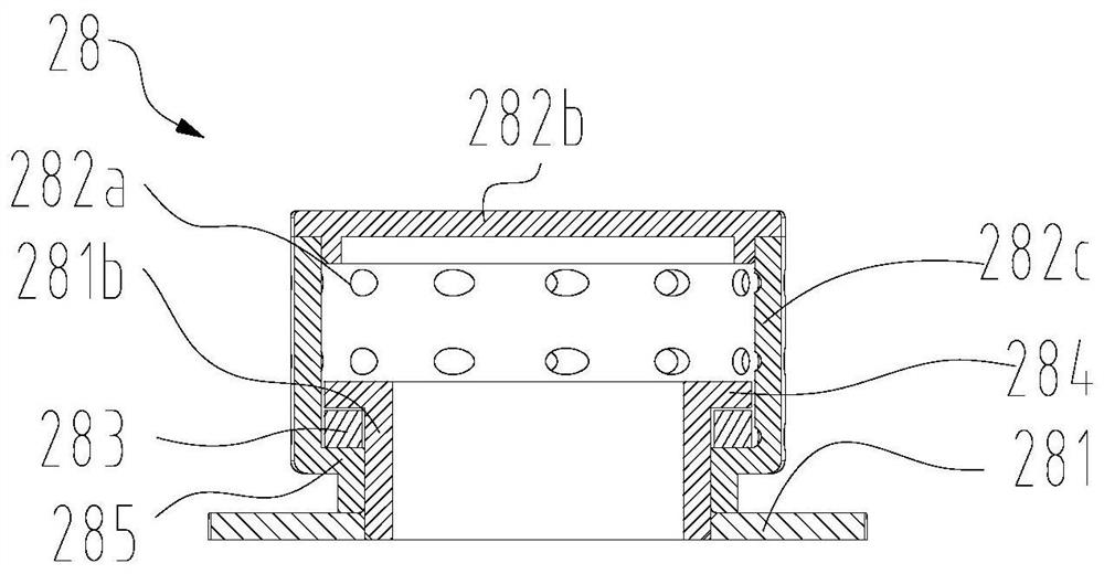
[0045]see in conjunction Figure 1 to Figure 12 As shown, according to the embodiment of the present application, the exhaust oil separation structure includes a base 281 and an oil separation cylinder 282. The oil separation cylinder 282 is rotatably mounted on the base 281 and can form an axial limit relative to the base 281. The oil separation cylinder 282 The top is sealed, and a through hole 282a is opened on the side wall of the oil separator cylinder 282. An acute angle θ is formed between the extension direction of the through hole 282a and the first plane. The first plane is the center of the outer opening of the through hole 282a and the oil separator cylinder at the same time. The vertical plane of the central axis of 282.

[0046] The exhaust oil separation structure of the present application is arranged at the exhaust port of the pump body structure inside the compressor, and the oil separation cylinder 282 of the exhaust oil separation structure can be lifted by...


PUM


Abstract

The invention provides an exhaust oil separation structure, a compressor and an air conditioner. The exhaust oil separation structure comprises a base (281) and an oil separation cylinder (282), the oil separation cylinder (282) can be rotationally installed on the base (281) and can form axial limiting relative to the base (281), the top of the oil separation cylinder (282) is sealed, a through hole (282a) is formed in the side wall of the oil separation cylinder (282), and an acute included angle theta is formed between the extension direction of the through hole (282a) and a first plane. The first plane is a vertical plane passing through the center of an outer side opening of the through hole (282a) and the central axis of the oil separation cylinder (282) at the same time. According to the exhaust oil separation structure, the size of the compressor can be reduced, the internal space of the compressor is effectively utilized, and the oil separation efficiency and the oil separation effect are improved.

Description

technical field [0001] The application relates to the technical field of air conditioning, in particular to an exhaust oil structure, a compressor and an air conditioner. Background technique [0002] The scroll compressor is mainly composed of parts such as a shell, a compression mechanism, a support mechanism, a drive mechanism, a working fluid suction pipe, and a working fluid discharge pipe. The compression mechanism is composed of an orbiting scroll part and a fixed scroll part. The driving mechanism includes a stator assembly and a crankshaft-rotor assembly. The crankshaft drives the movable scroll. Since the movable scroll is provided with an anti-rotation mechanism, the movable scroll rotates in translation relative to the fixed scroll. The volume of the compression chamber defined by the spiral scroll of the fixed scroll part and the spiral scroll of the movable scroll part gradually decreases, and the pressure of the refrigerant in the chamber continues to rise, s...

Claims


Application Information

Patent Timeline
Patent Type & Authority Applications(China)
IPC IPC(8): F04C29/02F04C29/00F04C18/02
CPCF04C18/0215F04C18/0246F04C29/00F04C29/026F04C29/028F04C2240/50F04C2240/56
Inventor 胡余生魏会军徐嘉单彩侠杨震郭求和
Owner ZHUHAI GREE REFRIGERATION TECH CENT OF ENERGY SAVING & ENVIRONMENTAL PROTECTION
Why Eureka
Try Eureka