Distributed optical fiber Raman sensing system and method for gas pipeline network leakage

A distributed optical fiber and Raman sensing technology, applied in the pipeline system, gas/liquid distribution and storage, fluid tightness testing, etc., can solve the problem of incompatibility between sensing distance and spatial resolution, resolution and sensing The distance cannot be taken into account, the temperature change is difficult to be detected, etc., to achieve the effect of optimizing spatial resolution, improving accuracy, and eliminating random noise

Active Publication Date: 2022-05-24
TAIYUAN UNIV OF TECH
View PDF14 Cites 0 Cited by
  • Summary
  • Abstract
  • Description
  • Claims
  • Application Information

AI Technical Summary

Problems solved by technology

At present, the positioning method of the distributed optical fiber Raman sensing system is optical time domain reflection technology, but due to the limitation of the pulse width of the light source, the sensing distance and spatial resolution cannot be balanced, and the optimal spatial resolution is only 1m
Since the leakage of the pipeline network will lead to changes in the temperature of the leakage location, the leakage of the pipeline network can be located through distributed temperature measurement, but when the spatial resolution of the distributed Raman sensing system in the prior art is large , the extremely small range of temperature changes caused by leakage is difficult to detect
[0005] Based on this, the present invention proposes a distributed optical fiber Raman sensing system and temperature demodulation method based on reconstruction layered analysis, which can solve the problem that the spatial resolution and sensing distance of the existing distributed optical fiber Raman sensing system cannot be balanced It is expected that the spatial resolution of the system will be increased to 1 cm, which will meet the needs of gas pipeline network leak detection.

Method used


Image

  • Distributed optical fiber Raman sensing system and method for gas pipeline network leakage
  • Distributed optical fiber Raman sensing system and method for gas pipeline network leakage
  • Distributed optical fiber Raman sensing system and method for gas pipeline network leakage

Examples


Embodiment Construction

[0028] In order to make the purposes, technical solutions and advantages of the embodiments of the present invention clearer, the technical solutions in the embodiments of the present invention will be described clearly and completely below. Obviously, the described embodiments are part of the embodiments of the present invention, not All the embodiments; based on the embodiments of the present invention, all other embodiments obtained by those of ordinary skill in the art without creative work, all belong to the protection scope of the present invention.

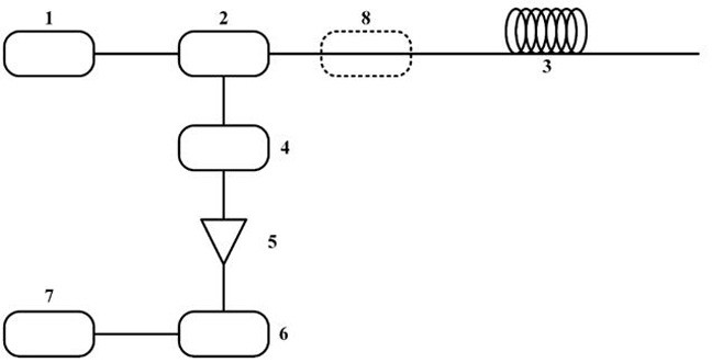
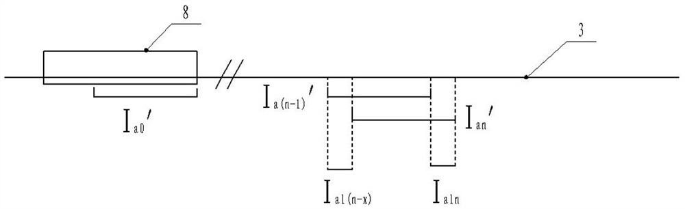
[0029] like figure 1 As shown, the embodiment of the present invention provides a distributed optical fiber Raman sensing system for gas pipeline network leakage. sensory device. The device includes a pulsed laser 1, a wavelength division multiplexer 2, a sensing fiber 3, an avalanche photodetector 4, an amplifier 5, a high-speed data acquisition card 6, a computer 7, and a constant temperature tank 8; the peak output powe...


PUM

PropertyMeasurementUnit
wavelengthaaaaaaaaaa

Abstract

The invention belongs to the technical field of distributed Raman optical fiber sensing, and discloses a distributed optical fiber Raman sensing system and method for pipe network leakage. The device includes a pulse laser, a wavelength division multiplexer, a sensing fiber, and a photoelectric detection The pulse laser output by the pulse laser is incident on the sensing fiber after passing through the wavelength division multiplexer. For detection, a part of the sensing fiber is set in a constant temperature tank, and the constant temperature tank is used for constant temperature control of the sensing fiber located therein; the signal detected by the photodetector is collected and demodulated by the data acquisition system to obtain the sensor Distributed temperature field information along the optical fiber. The invention optimizes the system resolution and improves the measurement accuracy.

Description

technical field [0001] The invention belongs to the technical field of distributed Raman optical fiber sensing, in particular to a distributed optical fiber Raman sensing system oriented to pipeline network leakage, which takes both long sensing distance and high spatial resolution into consideration. Background technique [0002] Pipeline transportation has become the lifeblood of modern industry and national economy. With the development of the gas pipeline network industry, the problem of safety monitoring of the gas pipeline network is becoming more and more serious. The gas pipeline network is gradually aging with the continuous growth of the service period, which leads to the hidden danger of leakage in the gas pipeline network. If it is allowed to develop, it will lead to major safety accidents. However, the current single-point, multi-probe, and single-parameter sensors cannot meet the large-scale and long-distance detection requirements of pipeline network transpor...

Claims


Application Information

Patent Timeline
Patent Type & Authority Patents(China)
IPC IPC(8): G01K11/324G01M3/00F17D5/06
CPCG01K11/32G01M3/002F17D5/06
Inventor 李健许扬周新新张明江尹子彤王晨懿冯凯
Owner TAIYUAN UNIV OF TECH
Why Eureka
Try Eureka