A method for measuring and controlling vibration and noise of a magnetron reactor

A magnetic control reactor, vibration and noise technology, applied in the direction of transformer/inductor noise damping, instruments, measuring devices, etc., can solve the problems of large vibration of the oil tank wall, poor adjustability, and affecting the quality of life of surrounding residents, so as to overcome the parameters Choose difficult, easy-to-maintain effects

Active Publication Date: 2022-05-17
ELECTRIC POWER RES INST OF STATE GRID ZHEJIANG ELECTRIC POWER COMAPNY
View PDF0 Cites 0 Cited by
  • Summary
  • Abstract
  • Description
  • Claims
  • Application Information

AI Technical Summary

Problems solved by technology

Due to its working principle and the particularity of the iron core structure, the noise problem of the magnetron reactor is becoming more and more serious, and the near-field sound pressure level generated reaches 75-80dB(A), which makes the noise in the substation and other places exceed the standard, and affects the quality of life of the surrounding residents.
[0003] The noise of the magnetron reactor comes from the magnetostriction of the iron core, and the rigid connection between the iron core and the fuel tank is generally adopted, and the vibration is basically not attenuated after being transmitted to the fuel tank, resulting in a large vibration of the fuel tank wall
At present, the general noise reduction measures are to change the connection between the iron core and the fuel tank to a flexible connection or to use a sound insulation cover made of sound-absorbing materials through the installation of spring vibration isolators. The reduction effect of the equipment varies greatly, and the latter will affect the daily maintenance of the equipment, especially the fire protection problem in the event of a fire accident.

Method used


Image

  • A method for measuring and controlling vibration and noise of a magnetron reactor
  • A method for measuring and controlling vibration and noise of a magnetron reactor
  • A method for measuring and controlling vibration and noise of a magnetron reactor

Examples


Embodiment Construction

[0067] The present invention will be further described in detail below with reference to the accompanying drawings. The following examples are only used to illustrate the technical solutions of the present invention more clearly, and cannot be used to limit the protection scope of the present invention.

[0068] The present invention is a method for measuring and controlling vibration and noise of a magnetron reactor, and the equipment involved includes an industrial computer 3, a vibration sensor 2, a damping adjustable shock absorber 5, a damping adjustable shock absorber control unit 4 and a magnetron reactor 1 ,like Figure 4 shown.

[0069] The vibration and noise measurement and control method of the magnetron reactor is as follows:

[0070] The vibration sensor is closely attached to the outer surface of the fuel tank of the magnetron reactor, and is used for collecting vibration noise signals.

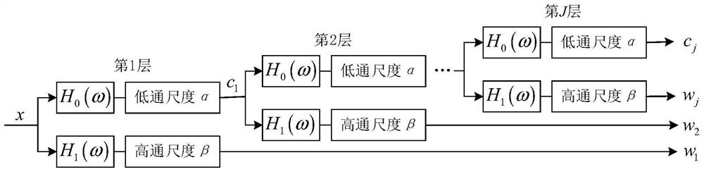
[0071] The industrial computer uses a signal decomposition algorithm ba...


PUM


Abstract

The invention discloses a method for measuring and controlling the vibration noise of a magnetron reactor. The technical solution adopted in the present invention is: the vibration sensor is closely attached to the outer surface of the fuel tank of the magnetron reactor, and is used to collect vibration and noise signals; the industrial computer processes the collected vibration and noise signals using a signal decomposition algorithm based on the vibration attribute of the signal, specifically Including: building a dictionary with different oscillation attributes by adjusting the quality factor, extracting the harmonic components in the vibration noise signal, and analyzing and processing the extracted vibration noise signal to generate a damping adjustment signal; the damping adjustment signal is transmitted to the damping adjustable shock absorber The control unit adjusts the damping parameters of the adjustable damping shock absorber to realize the regulation and control of the damping of the adjustable damping shock absorber. The invention uses the signal decomposition based on the signal oscillation property to establish a vibration detection and control method of the magnetic control reactor, thereby realizing the vibration reduction and noise reduction and safe operation of the magnetic control reactor.

Description

technical field [0001] The invention belongs to the field of reactive power compensation of power systems, relates to a magnetron reactor, in particular to a method for measuring and controlling vibration and noise of the magnetron reactor. Background technique [0002] Magnetron reactor is a kind of reactive power compensation equipment widely used in high-voltage power transmission system. It has excellent working characteristics. It can not only improve the power factor and system stability of the grid, but also limit high-frequency voltage. In addition, compared with other reactive power compensation equipment, magnetron reactor has many advantages such as low cost, high efficiency, long life and so on. Due to its working principle and the particularity of its iron core structure, the noise problem of the magnetron reactor is becoming more and more serious, and the generated near-field sound pressure level reaches 75-80dB(A), which makes the noise in substations and othe...

Claims


Application Information

Patent Timeline
Patent Type & Authority Patents(China)
IPC IPC(8): G05D19/02G01H17/00H01F27/33G06K9/00G06K9/62
CPCG05D19/02G01H17/00H01F27/33G06V10/40G06V10/513G06F2218/08G06F18/28Y02E40/30
Inventor 郑一鸣李晨金凌峰徐华邵先军李贤良王劭鹤陈孝信杨智蔺家骏姜炯挺贡春艳杨圣利何建伟杨富文
Owner ELECTRIC POWER RES INST OF STATE GRID ZHEJIANG ELECTRIC POWER COMAPNY
Why Eureka
Try Eureka