Distributed drainage method

A distributed, traffic-draining node technology, applied in the field of big data, can solve the problems of difficult deployment and maintenance of traffic-draining services, increased labor of operation and maintenance personnel, etc., so as to solve the problems of efficiency and cost, and improve the ability of traffic-draining.

Active Publication Date: 2021-03-26
神州灵云(北京)科技有限公司
View PDF3 Cites 0 Cited by
  • Summary
  • Abstract
  • Description
  • Claims
  • Application Information

AI Technical Summary

Problems solved by technology

However, due to the explosive growth of users, the horizontal expansion of production servers is increasing, and the analysis and judgment of the network status and storage status of more and more servers will greatly increase the workload of operation and maintenance personnel. Maintenance will become more and more difficult

Method used


Image

  • Distributed drainage method

Examples


Embodiment Construction

[0021] In order to make the objects, technical solutions, and advantages of the present invention, the embodiments of the present invention will be further described in detail below with reference to the accompanying drawings.

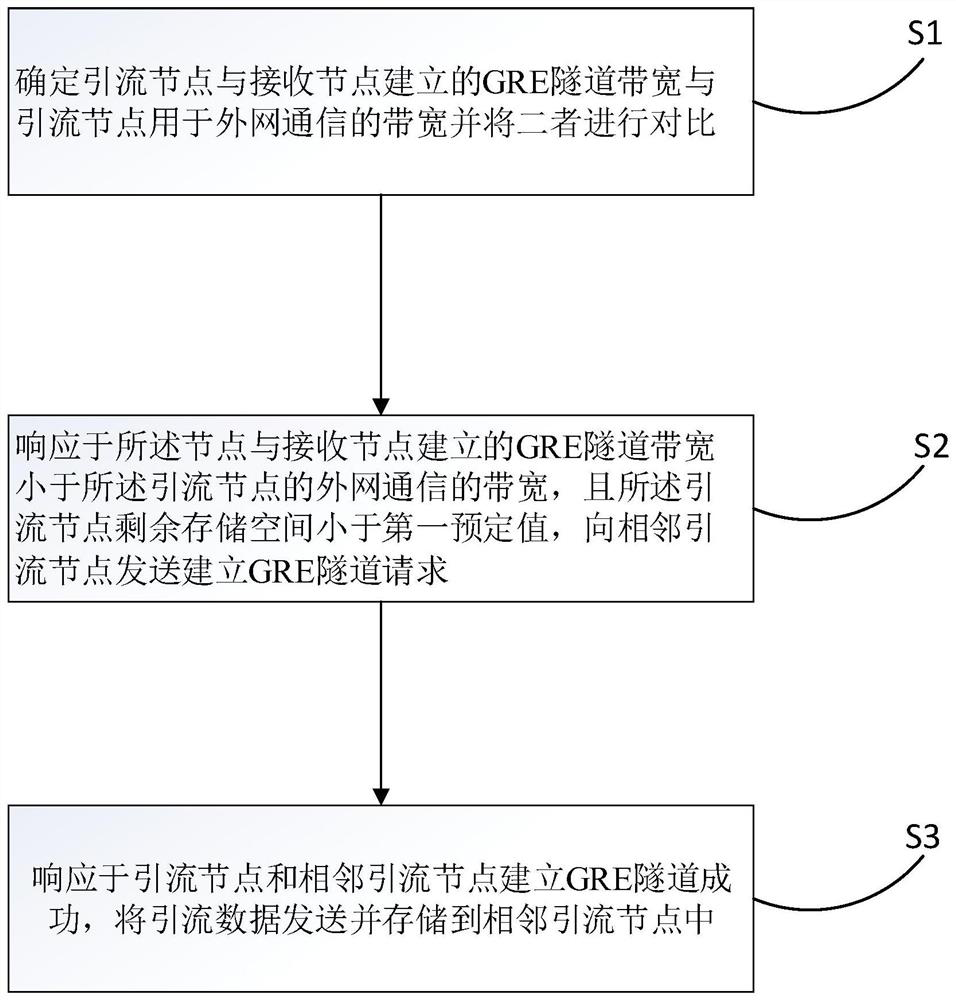
[0022] Such as figure 1 As shown, the present invention proposes a distributed drainage method, including:

[0023] S1, determine the GRE tunnel bandwidth established by the drain node and the receiving node and the drainage node for the bandwidth of the external network communication and compare the two;

[0024] S2, in response to the bandwidth of the GRE tunnel bandwidth established by the node and the receiving node is smaller than the bandwidth of the external network communication of the drain node, and the remaining storage space of the drain node is smaller than the first predetermined value, sending a GRE tunnel to the adjacent drainage node request;

[0025] S3, in response to the drainage node and adjacent drainage nodes establish a GRE tunnel s...


PUM


Abstract

The invention discloses a distributed drainage method comprises the following steps: determining a GRE tunnel bandwidth established by a drainage node and a receiving node and a bandwidth of the drainage node for external network communication, and comparing the two bandwidths; in response to the fact that the bandwidth of a GRE tunnel established by the node and a receiving node is smaller than the bandwidth of external network communication of the drainage node and the residual storage space of the drainage node is smaller than a first preset value, sending a GRE tunnel establishment requestto an adjacent drainage node; in response to successful establishment of the GRE tunnel between the drainage node and the adjacent drainage node, sending and storing the drainage data into the adjacent drainage node. Through the distributed drainage method provided by the invention, the drainage network and the storage space of the drainage system formed by the plurality of drainage nodes and thereceiving nodes can be adaptively and fully utilized, and the drainage task can be efficiently executed.

Description

Technical field [0001] The present invention relates to the field of large data, and more particularly to a distributed drainage method for data drainage. Background technique [0002] In recent years, it is benefited from the substantial network hardware performance, and the extensive implementation of fiber optic communications. The current network transmission speed has a quality leap. The number of domestic netizens is in the premise of intelligent equipment and high-speed network. Increased, and the size of network data has changed, and all kinds of network information frequently exchange between servers and clients or browsers. At the same time, expanded data also brings a new service type. To address network security, it is often necessary to analyze the communication data on the server, but the data is analyzed for the calculation capabilities using the production server, because expensive server usage fees are obviously Not very realistic. [0003] Therefore, it is commo...

Claims


Application Information

Patent Timeline
Patent Type & Authority Applications(China)
IPC IPC(8): H04L12/24H04L29/08H04L12/46
CPCH04L41/14H04L67/10H04L12/4633H04L67/141Y02D30/70
Inventor 曹中玉方奕
Owner 神州灵云(北京)科技有限公司
Why Eureka
Try Eureka