
Anti-water-seepage electrified cabinet

A motor-connected and water-proof technology, which is applied in the direction of casings/cabinets/drawer components, electrical equipment casings/cabinets/drawers, electrical components, etc., can solve the problem of burning electrical cabinets, leakage, and no fire extinguishers, etc. problems, to avoid damp short circuit and reduce losses

Inactive Publication Date: 2021-03-26
杭州凌亲数码科技有限公司
View PDF2 Cites 0 Cited by
  • Summary
  • Abstract
  • Description
  • Claims
  • Application Information

AI Technical Summary

Problems solved by technology

[0002] In our daily life, the electrical cabinets are generally distributed outdoors, and the side walls of the electrical cabinets are often provided with cooling vents to ventilate and dissipate heat. However, in rainy days, rainwater easily enters the cabinet, and the electrical cabinets are usually placed directly on the ground. On rainy days, rainwater is easy to accumulate on the ground, and the accumulated water is easy to seep into the inside of the cabinet from the bottom of the electric cabinet, which will make the internal components of the electric cabinet damp and short-circuit, and even cause safety accidents such as electric leakage. Generally, there are no fire extinguishers around the outdoor electric cabinet. The fire of internal components can easily lead to the burning of the entire electrical cabinet. The anti-seepage water electrical cabinet described in the present invention can solve the above problems

Method used


Image

  • Anti-water-seepage electrified cabinet
  • Anti-water-seepage electrified cabinet
  • Anti-water-seepage electrified cabinet

Examples


Embodiment Construction

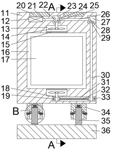
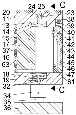
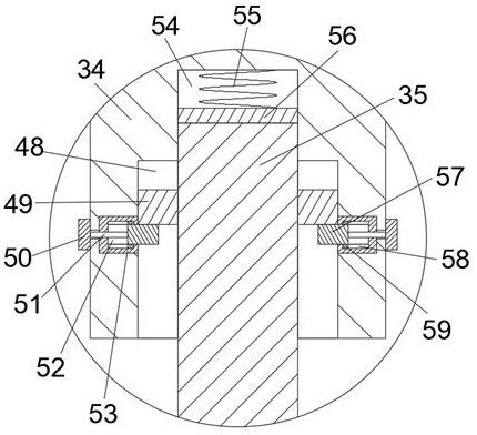
[0016] Combine below Figure 1-4 The present invention is described in detail, and for convenience of description, the orientations mentioned below are now stipulated as follows: figure 1 The up, down, left, right, front and back directions of the projection relationship itself are the same.

[0017] An anti-seepage water electrical cabinet according to the present invention includes an electrical cabinet body 11, a working chamber 16 through which the front and back are connected is arranged on the lower side of the electrical cabinet body 11, and a fire extinguishing device is arranged on the front side of the working chamber 16, so that The fire extinguishing device includes a rotating chamber 38 connected to the front side of the upper end wall of the working chamber 16 and with the opening facing forward. A rotating shaft 39 is arranged to rotate between the center of the left and right end walls of the rotating chamber 38. The outer surface of the rotating shaft 39 is T...


PUM


Abstract

The invention discloses an anti-water-seepage electrified cabinet. The cabinet comprises an electrified cabinet body, the lower side in the electrified cabinet body is provided with a working cavity which is through front and back, the front side of the working cavity is provided with a fire extinguishing device, and the fire extinguishing device comprises a rotating cavity which is arranged on the front side of the upper end wall of the working cavity in a communicating mode and is provided with a forward opening; a rotating shaft is rotatably arranged between the centers of the left end walland the right end wall of the rotating cavity, a rotating connecting block is fixedly arranged in the middle of the outer circle face of the rotating shaft, a switch door located in the working cavity is fixedly arranged at the lower end of the rotating connecting block, a fire extinguishing sliding groove is formed in the switch door, and a fire extinguishing sliding block is slidably arranged in the fire extinguishing sliding groove; and a fire extinguisher is fixedly arranged at the center of the interior of the fire extinguishing sliding block. According to the invention, a relatively high base is erected, and the whole power-on cabinet is fixed on the base through a limiting device, so that water accumulated on the ground is prevented from entering the power-on cabinet body in rainydays.

Description

technical field [0001] The invention relates to the field of electrical cabinets, in particular to an anti-seepage water electrical cabinet. Background technique [0002] In our daily life, the electrical cabinets are generally distributed outdoors, and the side walls of the electrical cabinets are often provided with cooling vents to ventilate and dissipate heat. However, in rainy days, rainwater easily enters the cabinet, and the electrical cabinets are usually placed directly on the ground. On rainy days, rainwater is easy to accumulate on the ground, and the accumulated water is easy to seep into the inside of the cabinet from the bottom of the electric cabinet, which will make the internal components of the electric cabinet damp and short-circuit, and even cause safety accidents such as electric leakage. Generally, there are no fire extinguishers around the outdoor electric cabinet. The fire of internal components can easily lead to the burning of the entire power suppl...

Claims


Application Information

Patent Timeline
Patent Type & Authority Applications(China)
IPC IPC(8): H05K5/02H05K7/20A62C3/16
CPCA62C3/16H05K5/0204H05K5/0213H05K5/0234H05K7/20145
Inventor 孟晶梅
Owner 杭州凌亲数码科技有限公司
Learn More