
Gluing plate capable of achieving uniform gluing and coating

A technology of glue plate and glue coating, which is applied to the device, coating, climate sustainability and other directions of coating liquid on the surface, which can solve the problems of increasing glue amount, increasing processing complexity, gram weight, etc., and improving the connection and sealing. The effect of improving the uniformity of sizing and sizing and reducing the production cost

Active Publication Date: 2021-03-30
FUJIAN HENGAN HLDG CO LTD +2
View PDF5 Cites 2 Cited by
  • Summary
  • Abstract
  • Description
  • Claims
  • Application Information

AI Technical Summary

Problems solved by technology

[0002] Most of the glue feed grooves in the back glue scraper lip of the sizing board provided by the existing manufacturers adopt a "T" structure, and the coating uniformity of multiple glue sizing areas cannot be effectively controlled during the production process, resulting in back glue The defect of large fluctuation range of adhesive strength, especially for the product specifications of the 3 sizing areas, the weight of the 2nd sizing area is obviously high. Specifically, when the equipment is initially running, the weight of the 3 sizing areas The square gram weight can basically be kept the same, but as the running time goes by, after 1 day, the other two glue inlets except the second glue inlet will gradually reduce the amount of glue, while the second glue inlet will Gradually increase the amount of glue; if the valve needle control of each glue inlet independent system is adopted, the selection size of the glue gun needs to be increased, the processing complexity will increase, and the number of configurations will also increase accordingly, which will increase the overall cost of equipment configuration

Method used


Image

  • Gluing plate capable of achieving uniform gluing and coating
  • Gluing plate capable of achieving uniform gluing and coating
  • Gluing plate capable of achieving uniform gluing and coating

Examples


Embodiment 1

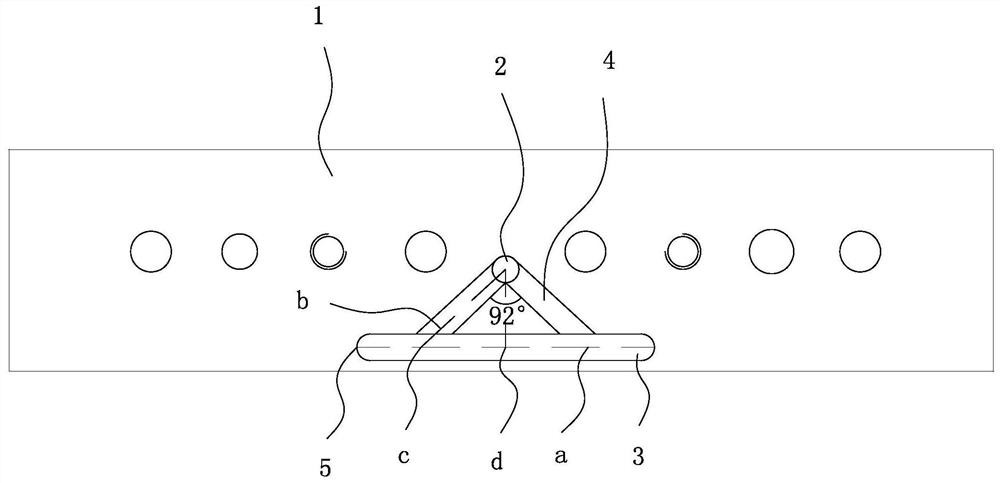
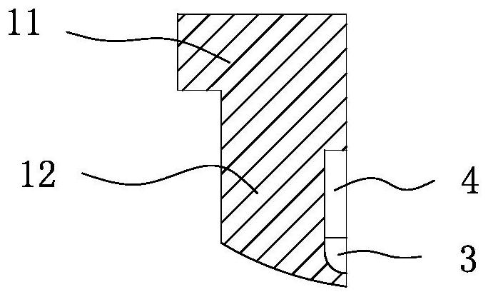
[0021] refer to figure 1 and figure 2 As shown, a sizing board with uniform sizing coating includes a sizing board body 1, and the sizing board body 1 includes a mounting portion 11 and an adhesive wiper lip 12 arranged on the mounting portion 11. The scraper lip 12 is provided with a glue inlet 2 and a sizing groove 3 for coating on the coating 10, the diameter of the glue inlet 2 is 3mm, and the depth of the glue inlet 2 is 3mm, defined Extending along the length direction of the sizing groove 3 is a transverse direction, and extending along its width direction is a longitudinal direction. The transverse length dimension of the sizing groove 3 is 33 mm, and the longitudinal width dimension of the sizing groove 3 is 3 mm. The depth of the sizing groove 3 is 1.5 mm. Two glue feeding grooves 4 connecting the two are provided between the glue inlet 2 and the sizing groove 3. The vertical line is axisymmetrically arranged, and the angle between the two sizing grooves 4 is 92°....

Embodiment 2

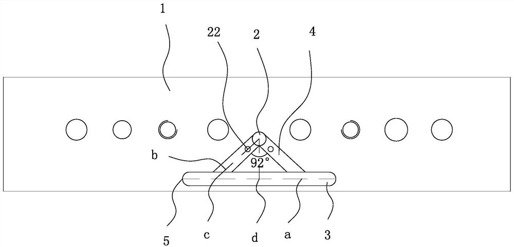
[0031] refer to image 3 , Figure 4 and Figure 5 As shown, the present embodiment 2 is further improved on the basis of embodiment 1, and its difference from embodiment 1 is technically characterized in that: the two glue feeding grooves 4 are provided with the flow for adjusting the flow of hot melt glue in the glue feeding groove 4. The adjustment mechanism of the amount of glue, the adjustment structure includes a threaded hole 20 located at the bottom of the glue feeding groove 4, the threaded hole 20 is internally threaded with a threaded rod 21, and the threaded rod 21 is located at one end of the glue feeding groove 4. There is a blocking block 22, by rotating the threaded rod 21, the position of the blocking block 22 in the glue feeding groove 4 is adjusted. Specifically, the threaded hole 20 includes the first threaded hole 201 and the The second threaded hole 202, the aperture size of the first threaded hole 201 is smaller than the aperture size of the second thr...

Embodiment 3

[0033] refer to Figure 6 and Figure 7As shown, the third embodiment is improved on the basis of the second embodiment, and the technical feature of its difference from the second embodiment is that: the sizing tank 3 is provided with a coating rubber plate 30 made of rubber, and the coating The lower end of the cloth rubber plate 30 extends to the outside and is provided with a coating groove 31, and its upper end is embedded on the plug 23, and the angle of the coating rubber plate 30 is adjusted by the movement of the plug 23, and the coating rubber plate 30 is The coating tank 31 is bent downward to form an arc structure 7, so that in the sizing coating 10, the coating tank 31 can be attached to the coating 10 for sizing, and the coating 10 is in the conveying process. The middle tension force changes, by extruding the coating rubber plate 30, it produces elastic deformation, and then better maintains the tension force of the coating 10, forming a better sizing environme...


PUM


Abstract

The invention relates to a gluing plate which is simple in structure, low in processing cost and capable of achieving uniform gluing and coating. The gluing plate comprises a gluing plate body, the gluing plate body comprises a mounting part and a back glue scraping lip arranged on the mounting part, the back glue scraping lip is provided with a glue inlet hole and a gluing groove for coating, thelength direction of the gluing groove is defined as the transverse direction, the width direction of the gluing groove is defined as the longitudinal direction, two glue inlet grooves communicated with the glue inlet and the gluing groove are formed between the glue inlet and the glue applying groove, the two glue inlet grooves are arranged in an axial symmetry manner along the perpendicular bisector of the gluing groove, and the included angle between the two glue inlet grooves is 92 degrees; and semi-arc structures are arranged at the two transverse ends of the gluing groove, the distancesbetween the transverse end of the gluing groove and the intersection points of the transverse central axis of the gluing groove and the central axes of the glue inlet grooves are equal to the distances between the midpoint of the gluing groove and the intersection points of the transverse central axis of the gluing groove and the central axes of the glue inlet grooves, the depth of the glue inletgrooves is 1.5 mm, and the width of the glue inlet grooves is 2.5 mm.

Description

technical field [0001] The invention relates to a sized board coated with uniform sizing. Background technique [0002] Most of the glue feed grooves in the back glue scraper lip of the sizing board provided by the existing manufacturers adopt a "T" structure, which failed to effectively control the coating uniformity of multiple glue sizing areas during the production process, resulting in back glue The defect of large fluctuation range of adhesive strength, especially for the product specifications of the 3 sizing areas, the weight of the 2nd sizing area is obviously high. Specifically, when the equipment is initially running, the weight of the 3 sizing areas The square gram weight can basically be kept the same, but as the running time goes by, after 1 day, the other two glue inlets except the second glue inlet will gradually reduce the amount of glue, while the second glue inlet will Gradually increase the amount of glue; if the valve needle control of each glue inlet i...

Claims


Application Information

Patent Timeline
Patent Type & Authority Applications(China)
IPC IPC(8): B05C1/04
CPCB05C1/04Y02P70/50
Inventor 许宗清
Owner FUJIAN HENGAN HLDG CO LTD
Features
  • Generate Ideas
  • Intellectual Property
  • Life Sciences
  • Materials
  • Tech Scout
  • Unparalleled Data Quality
  • Higher Quality Content
  • 60% Fewer Hallucinations
Learn More