
Heat pump equipment convenient to install and use

A heat pump and equipment technology, applied in the field of heat pump equipment, can solve the problems of disadvantageous convenience of installation and use of heat pump equipment, troublesome installation and transfer of heat pump equipment, inconvenient disassembly and replacement of locations, etc. The effect of improving convenience and simple structure

Inactive Publication Date: 2021-03-30
天津丽茂源松节能技术有限公司
View PDF0 Cites 0 Cited by
  • Summary
  • Abstract
  • Description
  • Claims
  • Application Information

AI Technical Summary

Problems solved by technology

[0002] Air source heat pump is an energy-saving device that uses high-level energy to make heat flow from low-level heat source air to high-level heat source. It is a form of heat pump. , The heat contained in the soil and water is converted into usable high-level heat energy, so as to achieve the purpose of saving part of the energy consumption; the existing heat pump equipment is generally troublesome to install and transfer, which is not conducive to installation and use, and the existing heat pump equipment During installation, it is generally necessary to use the base for elevated installation to prevent the heat pump equipment from entering water or being damp, but the base needs to be constructed or manufactured outside, and it is very troublesome to operate during the installation process. It is also very inconvenient to disassemble and replace the position, which is not conducive to Improve the convenience of heat pump equipment installation and use

Method used


Image

  • Heat pump equipment convenient to install and use
  • Heat pump equipment convenient to install and use

Examples


Embodiment Construction

[0018] It should be noted that, in the case of no conflict, the embodiments of the present invention and the features in the embodiments can be combined with each other.

[0019] In describing the present invention, it should be understood that the terms "center", "longitudinal", "transverse", "upper", "lower", "front", "rear", "left", "right", The orientations or positional relationships indicated by "vertical", "horizontal", "top", "bottom", "inner", "outer", etc. are based on the orientation or positional relationships shown in the drawings, and are only for the convenience of describing the present invention Creation and simplification of description, rather than indicating or implying that the device or element referred to must have a specific orientation, be constructed and operate in a specific orientation, and therefore should not be construed as limiting the invention. In addition, the terms "first", "second", etc. are used for descriptive purposes only, and should no...


PUM


Abstract

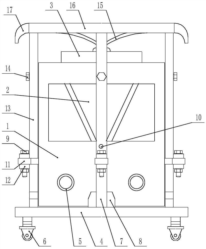
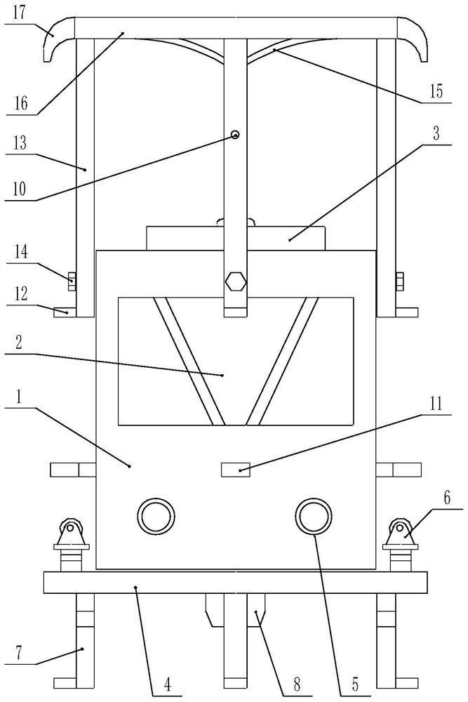
The invention provides heat pump equipment convenient to install and use. The heat pump equipment comprises a box body, a heat exchange mechanism arranged above the box body and a heat pump mechanismarranged below the box body, a shielding mechanism is arranged on the outer side of the box body, and the shielding mechanism comprises a lower protection frame arranged below the box body and an upper protection frame arranged above the box body; a lower supporting column is arranged on the side, facing the upper protection frame, of the lower protection frame, and a walking assembly is arrangedon the other side of the lower protection frame. at least four lower supporting columns are evenly arranged corresponding to the circumferential direction of the box body, upper supporting columns arearranged at the positions, corresponding to the lower supporting columns, of the upper protection frame, and a positioning assembly used for fixing the upper supporting columns is arranged on the boxbody. The heat pump equipment is simple in structure, easy to install and use, quite convenient to install, good in reliability and safety after being transported and installed, not prone to damage,capable of greatly reducing the installation and use cost of the heat pump equipment and beneficial to large-scale application and popularization.

Description

technical field [0001] The invention belongs to the field of heat pumps, and in particular relates to a heat pump device which is easy to install and use. Background technique [0002] Air source heat pump is an energy-saving device that uses high-level energy to make heat flow from low-level heat source air to high-level heat source. It is a form of heat pump. , The heat contained in the soil and water is converted into usable high-level heat energy, so as to achieve the purpose of saving part of the energy consumption; the existing heat pump equipment is generally troublesome to install and transfer, which is not conducive to installation and use, and the existing heat pump equipment During installation, it is generally necessary to use the base for elevated installation to prevent the heat pump equipment from entering water or being damp, but the base needs to be constructed or manufactured outside, and it is very troublesome to operate during the installation process. It...

Claims


Application Information

Patent Timeline
Patent Type & Authority Applications(China)
IPC IPC(8): F25B30/02F25B49/02F16M3/00F16M11/22
CPCF16M3/00F16M11/22F25B30/02F25B49/02
Inventor 苏志松
Owner 天津丽茂源松节能技术有限公司
Learn More