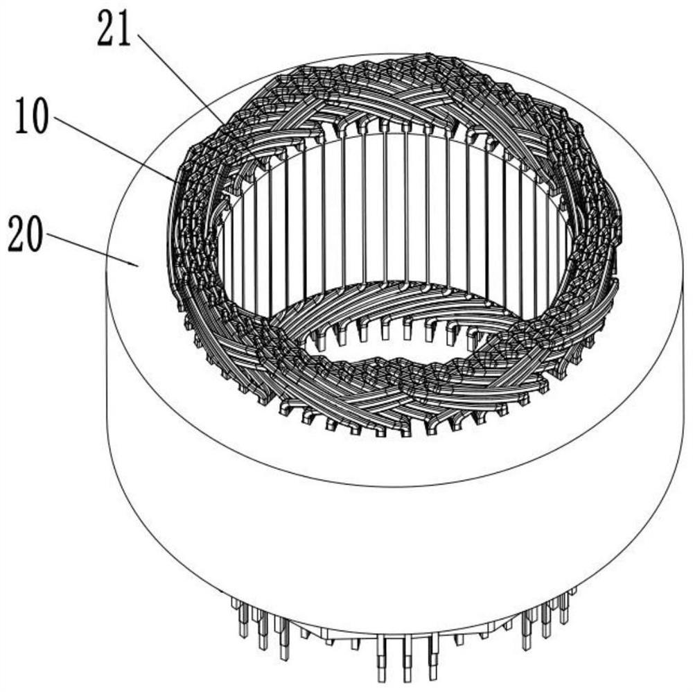
Motor stator winding, stator using same and motor

A motor stator and stator winding technology, which is applied to the shape/style/structure of winding and winding conductors, electric components, etc., can solve the problems of inconsistent twisting directions of hairpin coils, complex arrangement of stator windings, and low processing efficiency. The effect of reducing the complexity of the manufacturing process, increasing the sustainable operating power, and improving the processing efficiency

Active Publication Date: 2021-03-30
BORGWARNER POWERDRIVE SYST (TIANJIN) CO CHINA
View PDF9 Cites 3 Cited by
  • Summary
  • Abstract
  • Description
  • Claims
  • Application Information

AI Technical Summary

Problems solved by technology

[0003]The stator winding of the Hair-pin includes multiple hairpin coils, which penetrate into the slots of the stator core according to a certain arrangement to form the required The windings of single-phase motors or multi-phase motors. In the prior art, the number of slots per pole and phase of Hair-pin stator windings is greater than or equal to 2, and there are many types of hairpin coils used. In the structure of series connection between phases , the twisting directions of the welding ends of the hairpin coils on the same layer will be inconsistent or the slot spacing between the welding ends of different hairpin coils will be different after twisting, so the stator winding needs to use a large number of bus bars and bus bars to connect the branches of each phase winding , the arrangement of stator windings is complex, difficult to form, high production cost, and low processing efficiency

Method used


Image

  • Motor stator winding, stator using same and motor
  • Motor stator winding, stator using same and motor
  • Motor stator winding, stator using same and motor

Examples


Embodiment 1

[0129] Embodiment 1: as Figure 9 As shown, the number of 21 per pole and each phase slot is 2, and the 2 branches are arranged in series, the first coil group is on the same layer (7, 5) + the first second coil group is at a full distance (6) + the second second Coil group full distance (6) + the fourth coil group on the same layer (7, 5); the number of layers is 6, two second coil groups are arranged adjacently, and the second second coil group is located in the radial direction of the stator core The pitch between a welding end 303 of the conductor of the 4th layer and a welding end 303 of the conductor of the third layer in the radial direction of the stator core in the first second coil group is a long pitch of 7;

Embodiment 2

[0130] Embodiment 2: as Figure 10 As shown, the number of 21 per pole and each phase slot is 2, and the 2 branches are arranged in series, the first coil group is on the same layer (7, 5) + the first second coil group is at a full distance (6) + the second second Coil group full distance (6) + the fourth coil group on the same layer (7, 5); the number of layers is 6, two second coil groups are arranged adjacently, and the second second coil group is located in the radial direction of the stator core The pitch between a welding end 303 of the conductor of the 4th layer and a welding end 303 of the conductor of the third layer in the radial direction of the stator core in the first second coil group is short pitch 5;

Embodiment 3

[0131] Embodiment 3: as Figure 11 As shown, the number of 21 per pole and each phase slot is 2, and the 2 branches are arranged in series, the first coil group is on the same layer (7, 5) + the first second coil group is at a full distance (6) + the second second Long and short distances of the coil group (7, 5) + the same layer of the fourth coil group (7, 5); the number of layers is 6, two second coil groups are arranged adjacently, and the second second coil group is located in the stator core The pitch between a welding end 303 of the conductor on the fourth layer in the radial direction and a welding end 303 of the conductor on the third layer in the radial direction of the stator core in the first second coil group is a long pitch of 7;


PUM


Abstract

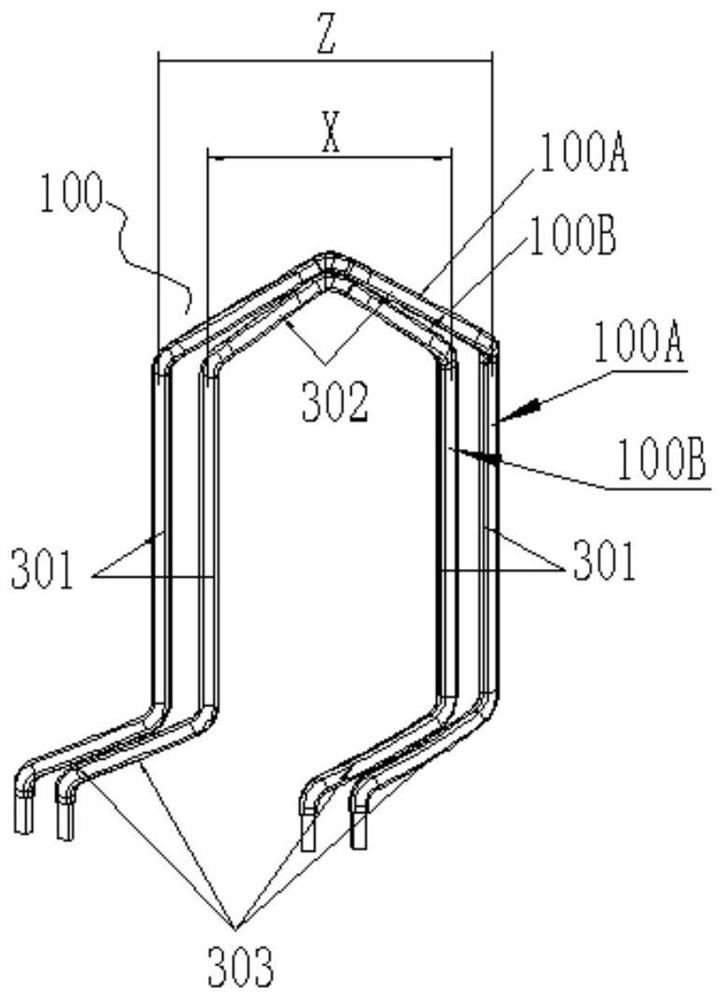
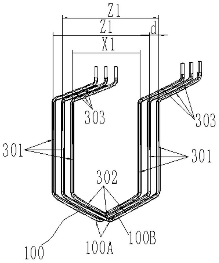
The invention provides a motor stator winding, a stator using the same and a motor, and belongs to the field of motors, the motor stator winding comprises a first coil assembly, a fourth coil assemblyand at least two second coil assemblies which are coaxially arranged, and the first coil assembly and the fourth coil assembly are arranged on the same layer of the radial inner side first layer andthe radial outer side first layer of a stator core; the first coil assembly and the fourth coil assembly have long and short distances, and in the same stator winding, the structures of the pluralityof second coil assemblies are the same or different; the pitch between the two welding ends of the two conductors welded with each other of the two second coil groups arranged adjacently is a long pitch; and the pitch between the second coil and the first coil group or between the second coil group and the fourth coil group and between the two welding ends of the two welded conductors is the wholepitch. The wiring mode is simple, the process is simplified, the complexity of the manufacturing process can be reduced, and the machining efficiency is improved.

Description

technical field [0001] The invention belongs to the field of motors, and relates to motor stator windings, stators and motors using the same. Background technique [0002] Winding motors designed with flat copper hairpin wires instead of traditional thin round wires are called Hair-pin winding motors. [0003] The stator winding of the Hair-pin includes a plurality of hairpin coils, and the multiple hairpin coils penetrate into the slots of the stator core according to a certain arrangement to form the windings of the required single-phase motor or multi-phase motor. In the prior art , the number of slots per pole and phase of the Hair-pin stator winding is greater than or equal to 2, and there are many types of hairpin coils used. In the structure of series connection between phases, there will be inconsistent twisting directions of the welding ends of the hairpin coils on the same layer Or different hairpin coils have different slot spacing after the welding ends are twis...

Claims


Application Information

Patent Timeline
Patent Type & Authority Applications(China)
IPC IPC(8): H02K3/28H02K3/12H02K3/04H02K3/24H02K3/50
CPCH02K3/28H02K3/12H02K3/04H02K3/24H02K3/50H02K2213/03
Inventor 王彦哲
Owner BORGWARNER POWERDRIVE SYST (TIANJIN) CO CHINA
Why Eureka
Try Eureka