Wireless client front-end equipment antenna adjusting method and wireless client front-end equipment

A technology of pre-equipment and adjustment method, which is applied in the direction of antenna support/installation device, antenna, antenna parts, etc., which can solve the problems of poor communication quality, high cost, and reduced product stability, so as to avoid poor signal quality, Convenience of antenna angle and improvement of installation efficiency

Active Publication Date: 2021-03-30
上海旷通科技有限公司
View PDF3 Cites 0 Cited by
  • Summary
  • Abstract
  • Description
  • Claims
  • Application Information

AI Technical Summary

Problems solved by technology

This makes it necessary to be operated by professionals during installation, otherwise the equipment cannot be used normally
As a result, higher costs have hindered the popularization of 5G customer front-end equipment, and reduced the network link speed and signal quality of home equipment.
[0003] For this reason, those skilled in the art try to solve the above technical problems by setting up omnidirectional antennas. However, although omnidirectional antennas do not have the problem of adjusting the angle, the signal quality of omnidirectional antennas is far from that of directional antennas. Communication in 5G communications poor quality
[0004] In addition, those skilled in the art also try to set the angle of the directional antenna to be adjustable. After the user completes the installation, the system will adjust the angle of the antenna to find the angle with the best signal quality, but this method adds more activities. The mechanical structure will reduce the stability of the product

Method used


Image

  • Wireless client front-end equipment antenna adjusting method and wireless client front-end equipment
  • Wireless client front-end equipment antenna adjusting method and wireless client front-end equipment

Examples


Embodiment Construction

[0028] The present invention will be described in detail below in conjunction with the accompanying drawings and specific embodiments. This embodiment is carried out on the premise of the technical solution of the present invention, and detailed implementation methods and specific operation processes are given, but the protection scope of the present invention is not limited to the following embodiments.

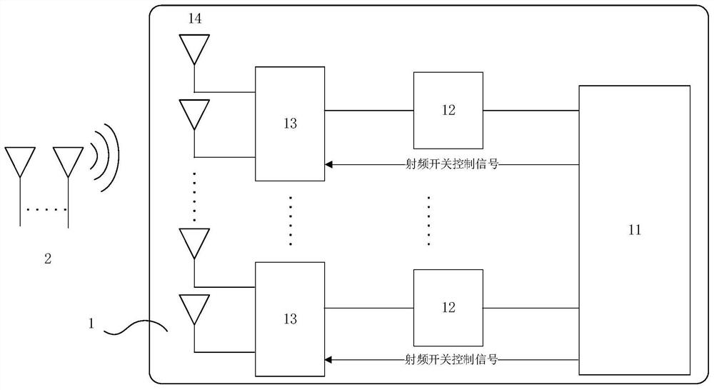
[0029] Such as figure 1 As shown, the present application provides a wireless client front-end equipment 1, including a processor 11, and a radio frequency module composed of a sequentially connected transmitting and receiving circuit 12, a radio frequency switch 13 and an antenna 14. There are multiple radio frequency modules, each Among the radio frequency modules, the antenna 14 in at least one radio frequency module is an omnidirectional antenna, and the antenna 14 in at least two radio frequency modules is a directional antenna, wherein the processor 11 also functions a...


PUM


Abstract

The invention relates to a wireless client front-end equipment antenna adjusting method and wireless client front-end equipment. The method comprises the steps: continuously obtaining the quality of a5G signal through an omnidirectional antenna and a directional antenna after entering a first state, and recording the optimal signal quality; and after entering the second state, continuously obtaining the quality of the 5G signal through the omnidirectional antenna and the directional antenna, comparing the quality with the optimal signal quality, and if the difference is smaller than a set error, outputting first confirmation information. Compared with the prior art, the omnidirectional antenna is utilized to participate in determining the optimal position and angle, and the process of special design is combined, so that a user can finish positioning installation of the wireless client front-end equipment by himself / herself, and the installation efficiency is greatly improved.

Description

technical field [0001] The invention relates to wireless communication equipment, in particular to a method for adjusting the antenna of a wireless client front-end device and the wireless client front-end device. Background technique [0002] In recent years, the distribution of 5G has become more and more widespread, and it has gradually begun to enter residential buildings. Unlike 4G and 3G, the distribution range of 5G signals is smaller. Therefore, when distributing terminals, 5G customer front-end equipment needs to be transferred to WiFi and other signals. , in the prior art, in order to obtain a better wireless signal transmission path, the 5G client front-end equipment generally adopts a directional mode. This makes it necessary to be operated by professionals during installation, otherwise the equipment cannot be used normally. As a result, higher costs have hindered the popularization of 5G customer front-end equipment, and reduced the network link speed and sign...

Claims


Application Information

Patent Timeline
Patent Type & Authority Applications(China)
IPC IPC(8): H04B1/40H04B17/309H01Q1/24H01Q3/08
CPCH04B1/40H04B17/309H01Q1/241H01Q3/08Y02D30/70
Inventor 王壮张帆王世洲严慧江刘曙新
Owner 上海旷通科技有限公司
Why Eureka
Try Eureka