
Connector auxiliary plugging and unplugging jig and connecting rod synchronous plugging and unplugging mechanism thereof

A technology of a plug-in mechanism and a connector, applied in the server field, can solve the problems of long time consumption, unfavorable plug-in operation, low operation efficiency, etc.

Active Publication Date: 2020-07-31
SUZHOU LANGCHAO INTELLIGENT TECH CO LTD
View PDF9 Cites 1 Cited by
  • Summary
  • Abstract
  • Description
  • Claims
  • Application Information

AI Technical Summary

Problems solved by technology

[0006] The pins of the high-speed signal connector are dense, the insertion force is strong, and the connection is tight, so the signal transmission is stable, but it is not conducive to the plug-in operation
At present, the high-speed signal connector is generally inserted manually, but this method is laborious and inefficient
As an improvement, there is a structure in the prior art that uses the principle of leverage to perform labor-saving operations, but only the same connector can be plugged in at a time, and the operation efficiency is too low, and because the distribution of high-speed signal connectors is large and Distribution locations vary, so worker labor is still high and time-consuming

Method used


Image

  • Connector auxiliary plugging and unplugging jig and connecting rod synchronous plugging and unplugging mechanism thereof
  • Connector auxiliary plugging and unplugging jig and connecting rod synchronous plugging and unplugging mechanism thereof
  • Connector auxiliary plugging and unplugging jig and connecting rod synchronous plugging and unplugging mechanism thereof

Examples


Embodiment Construction

[0034] The following will clearly and completely describe the technical solutions in the embodiments of the present invention with reference to the accompanying drawings in the embodiments of the present invention. Obviously, the described embodiments are only some, not all, embodiments of the present invention. Based on the embodiments of the present invention, all other embodiments obtained by persons of ordinary skill in the art without making creative efforts belong to the protection scope of the present invention.

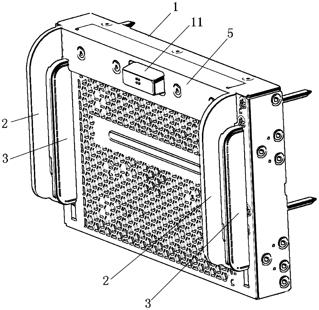
[0035] Please refer to figure 1 , figure 1 It is a schematic diagram of the overall structure of a specific embodiment provided by the present invention,

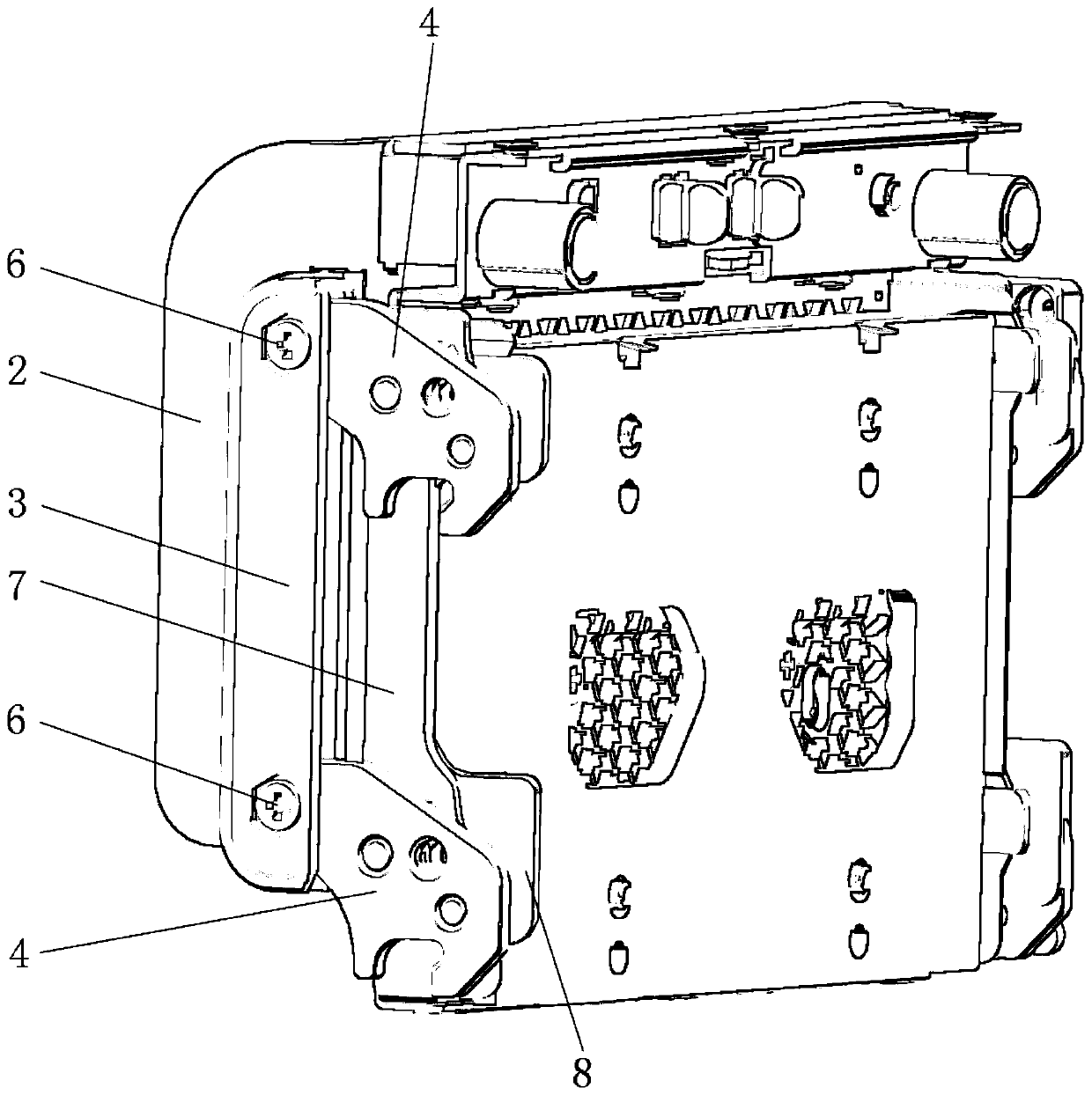
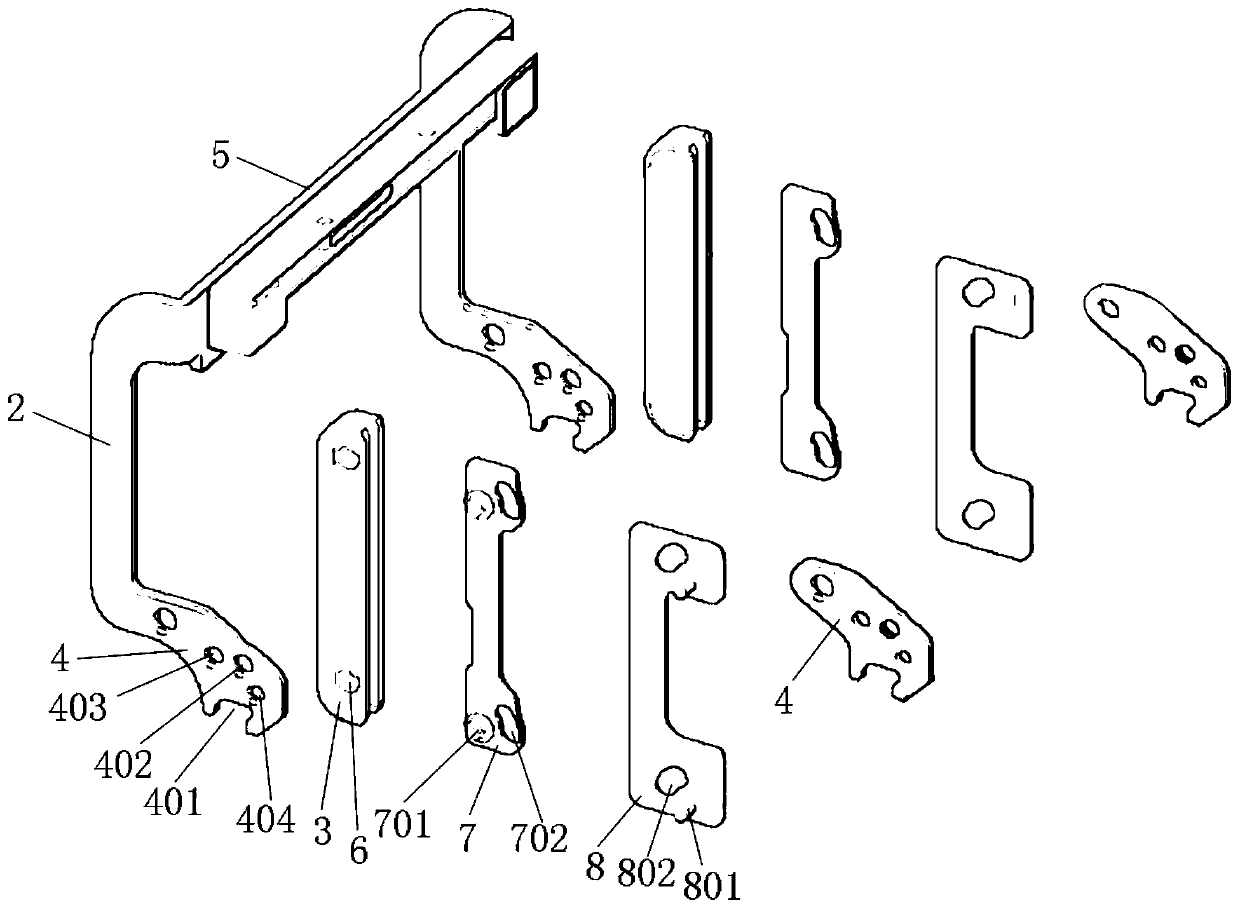
[0036] In a specific embodiment provided by the present invention, the connecting rod synchronous plug-in mechanism mainly includes a flipping connecting rod 2 , a synchronizing connecting rod 3 and claws 4 .

[0037] Wherein, the turning link 2 is arranged on the surface of the fixture housing 1 and can ...


PUM


Abstract

The invention discloses a connecting rod synchronous pulling and unplugging mechanism, which comprises a turnover connecting rod arranged on the surface of a jig shell in a turnover mode, a synchronous connecting rod fixedly connected to the rod body of the turnover connecting rod, and multiple clamping jaws connected to the synchronous connecting rod and used for clamping corresponding connectorsrespectively so as to apply force to pull and plug the connectors in a rotating mode, wherein a clamping groove used for clamping the connector is formed in the outer edge of each clamping jaw, and arotating center hole used for being matched with a centering pin shaft and reserved on the jig shell is formed in the surface of each clamping jaw. According to the invention, when the turnover connecting rod performs turnover motion, the synchronous connecting rod drives the clamping jaws to perform synchronous rotating motion with the respective rotating center holes as the rotating axes at thesame time, and then the clamping jaws synchronously complete plugging and unplugging operation of the respective corresponding connectors, so that the labor amount of workers and the labor cost are reduced, and the operation efficiency is improved. The invention also discloses a connector auxiliary plugging and unplugging tool, which has the above beneficial effects.

Description

technical field [0001] The invention relates to the technical field of servers, in particular to a synchronous plug-and-plug mechanism for connecting rods. The invention also relates to a jig for auxiliary plugging and unplugging of connectors. Background technique [0002] With the development of electronic technology in China, more and more electronic devices have been widely used. [0003] A server is an important part of electronic equipment and a device that provides computing services. Since the server needs to respond to and process service requests, generally speaking, the server should have the ability to undertake and guarantee services. According to the different types of services provided by the server, it is divided into file server, database server, application server, WEB server, etc. The main components of the server include processors, hard disks, memory, system buses, etc., which are similar to general-purpose computer architectures, but due to the need ...

Claims


Application Information

Patent Timeline
IPC IPC(8): H01R43/26
CPCH01R43/26H05K7/1485H05K7/1409
Inventor 余世茂杨杰尹秀忠张海龙
Owner SUZHOU LANGCHAO INTELLIGENT TECH CO LTD
Learn More