A Faraday Probe Array Based Ion Thruster Beam Testing System

An ion thruster and probe array technology, which is used in radiation measurement, instruments, measurement devices, etc., can solve problems such as insufficient collected data to reflect beam distribution, and achieve solutions to insulation degradation, simple positioning methods, and large amounts of data and information. Effect

Active Publication Date: 2017-11-03
LANZHOU INST OF PHYSICS CHINESE ACADEMY OF SPACE TECH
View PDF4 Cites 1 Cited by
  • Summary
  • Abstract
  • Description
  • Claims
  • Application Information

AI Technical Summary

Problems solved by technology

[0003] At present, the Faraday probes used to measure the beam divergence angle and the thruster vector deflection angle are generally point distribution or line distribution, and the collected data is not enough to reflect the beam current distribution, so multiple measurements are required

Method used


Image

  • A Faraday Probe Array Based Ion Thruster Beam Testing System
  • A Faraday Probe Array Based Ion Thruster Beam Testing System
  • A Faraday Probe Array Based Ion Thruster Beam Testing System

Examples


Embodiment Construction

[0039] The present invention will be described in detail below with reference to the accompanying drawings and examples.

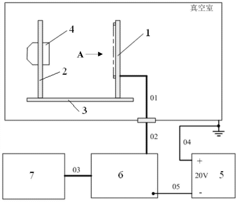
[0040] The invention provides a Faraday probe array-based ion thruster beam current testing system, such as figure 1 As shown, the system includes a Faraday probe array 1 , a thruster bracket 2 , a base plate 3 , a bias power supply 5 , a test circuit board 6 and a test computer 7 .

[0041] The measured ion thruster 4 is installed on the base plate 3 through the thruster bracket 2 , and the Faraday probe array 1 is installed on the base plate 3 . The nozzle of the ion thruster 4 is opposite to and parallel to the test surface of the Faraday probe array 1 . The center of the Faraday probe array 1 is on the extension line of the central axis of the ion thruster 4 .

[0042] In order to accurately ensure that the center of the Faraday probe array is on the central axis of the ion thruster, and the installation plane of the Faraday probe is parallel to the in...


PUM


Abstract

The invention discloses an ion thruster beam test system based on a Faraday probe array. Faraday probes are arranged in a surface array, all probe test signals are collected synchronously, and the amount of data information is large. A complete test and data processing can be completed in minutes. There is a shielding jacket on the outside of the ion current collection disk of each Faraday probe, which is used to shield the stray ions flying to the side of the ion current collection disk, so as to ensure that only the front side collects ions; the shielding jacket is directly in contact with the disc-shaped metal bracket through metal To achieve electrical connection, only one wire can be used to supply the bias voltage to the disc-shaped metal support. The biggest advantage of this method is that the number of probe leads is greatly reduced, the structure is simplified, and the reliability is improved.

Description

technical field [0001] The invention relates to the technical field of ion thruster beam current testing, in particular to an ion thruster beam current testing system based on a Faraday probe array. Background technique [0002] The ion thruster is the core unit of the ion propulsion system to generate thrust. In the development and testing of the ion thruster, it is necessary to test and analyze its beam distribution. By processing the beam distribution test data, the beam divergence angle, thruster Performance parameters such as vector deflection angle. [0003] At present, the Faraday probes used to measure the beam divergence angle and thruster vector deflection angle are generally point distribution or line distribution, and the collected data is not enough to reflect the beam current distribution, so multiple measurements are required. Therefore, it can be considered to arrange Faraday probes in a surface array. Moreover, when designing the structure, it is also nece...

Claims


Application Information

Patent Timeline
Patent Type & Authority Patents(China)
IPC IPC(8): G01T1/29
Inventor 张天平张伟文李得天唐福俊杨俊泰顾左崔铁民江豪成孟伟丁国宗
Owner LANZHOU INST OF PHYSICS CHINESE ACADEMY OF SPACE TECH
Why Eureka
Try Eureka