Laser thickness measurement method and device

A technology of laser thickness measurement and laser spot, which is applied in measurement devices, optical devices, instruments, etc., can solve the problems of displacement measurement system staying in the laboratory stage, slow execution of image processing algorithms, and unfavorable actual production. Signal-to-noise ratio and CCD conversion speed, elimination of ineffective cycles, fast effects

Active Publication Date: 2016-03-09
ZHEJIANG SCI-TECH UNIV
View PDF11 Cites 0 Cited by
  • Summary
  • Abstract
  • Description
  • Claims
  • Application Information

AI Technical Summary

Problems solved by technology

The measurement accuracy of the traditional non-contact optical measurement method mainly depends on the pixel size of the CCD, which is easily limited by the size of the CCD pixel. The cost of improving the measurement accuracy of the measurement system by increasing the CCD pixel is quite high, so people Proposed a sub-pixel spot center positioning technology using image processing software algorithm to improve measurement accuracy
However, due to the slow execution speed and poor real-time performance of the image processing algorithm, it is difficult to apply it to real-time online measurement, which is not conducive to the application in actual production.
[0003] The potential annual demand in the domestic laser thickness gauge market is more than a thousand units, and the market potential is great. Unfortunately, the current market is still dominated by foreign products, and most domestic research on CCD-based displacement measurement systems is still in the experimental stage. chamber stage

Method used


Image

  • Laser thickness measurement method and device
  • Laser thickness measurement method and device
  • Laser thickness measurement method and device

Examples


Embodiment Construction

[0047] The technical solution of the present invention will be further specifically described below through the embodiments and in conjunction with the accompanying drawings.

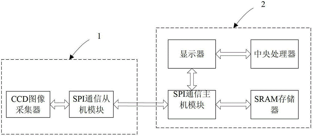
[0048] Such as figure 1 Shown is a laser thickness measuring device for implementing the thickness measuring method of the present invention, including a CCD signal acquisition system 1 and an ARM signal processing system 2, and a communication bus is connected between the CCD signal acquisition system 1 and the ARM signal processing system 2.

[0049]CCD signal acquisition system 1 includes a CCD image collector (including CCD image sensor and CCD image acquisition module) and a SPI communication slave module; ARM signal processing system 2 includes SPI communication master module, SRAM memory, central processing unit and display. The CCD image collector and the SPI communication slave module communicate with each other, the SPI communication slave module and the SPI communication master module communi...


PUM


Abstract

The invention discloses a laser thickness-measuring method and device. The method comprises the following steps of (1) collecting image data of a laser spot returned by a datum plane; (2) conducting preprocessing on the image data of the laser spot, then conducting coarse positioning, and obtaining a spot center pixel point xi after coarse positioning; (3) using the xi to serve as a center to confirm a mono-peak area, conducting fine positioning on a plurality of data points in the mono-peak area, and obtaining a spot center which is marked as x1 after the fine positioning; (4) again collecting the image data of the laser spot returned by an object to be measured, repeating the step (2) and the step (3) to obtain a spot center, which is marked as x2, of the object to be measured after fine positioning, and enabling displacement z of the spot centers of the object to be measured and the datum plane to be | x1-x2 |; and (5) calculating the thickness y of the object to be measured according to the displacement z. The method conducts processing based on a CCD algorithm and an embedded type ARM algorithm, and is high in speed, high in precision and capable of achieving on-line measuring.

Description

technical field [0001] The invention relates to the field of thickness measuring devices and methods, in particular to a laser thickness measuring method based on CCD and embedded ARM algorithm processing. Background technique [0002] Measurement plays an important role in human's daily life. With the rapid development of science and technology and industrial production, people have higher and higher requirements for measurement, and have begun to develop towards high speed, high precision, miniaturization, and intelligence. Especially today with the rapid development of science and technology, the requirements for the measurement accuracy of parts are getting higher and higher. Compared with traditional measurement methods, such as contact measurement, ultrasonic measurement, and X-ray measurement, the non-contact optical measurement method based on linear array CCD has the advantages of non-contact, high precision, fast response, strong adaptability, and low power consum...

Claims


Application Information

Patent Timeline
Patent Type & Authority Patents(China)
IPC IPC(8): G01B11/06
Inventor 黄静章涵博
Owner ZHEJIANG SCI-TECH UNIV
Why Eureka
Try Eureka