Heat dissipation structure of frequency converter group or multiple frequency converter group

A technology of heat dissipation structure and frequency converter, which is applied to the circuit layout of the supporting structure, the modification of power electronics, and the conversion device of output power, etc., which can solve the problems of increased cost, increased width or thickness of the control cabinet, and elevator control cabinets. Large volume and other issues, to achieve the effect of miniaturization and thin design

Pending Publication Date: 2021-03-30
HITACHI ELEVATOR CHINA
View PDF0 Cites 0 Cited by
  • Summary
  • Abstract
  • Description
  • Claims
  • Application Information

AI Technical Summary

Problems solved by technology

However, if the control cabinet needs to arrange multiple frequency converter groups, it is usually arranged side by side, resulting in an increase in the width or thickness of the control cabinet, so that the entire elevator control cabinet has a large volume and increases the cost
For machine room-less elevators and small machine room elevators, the size of the control cabinet has strict constraints, often forming a contradiction

Method used


Image

  • Heat dissipation structure of frequency converter group or multiple frequency converter group
  • Heat dissipation structure of frequency converter group or multiple frequency converter group

Examples


Embodiment 2

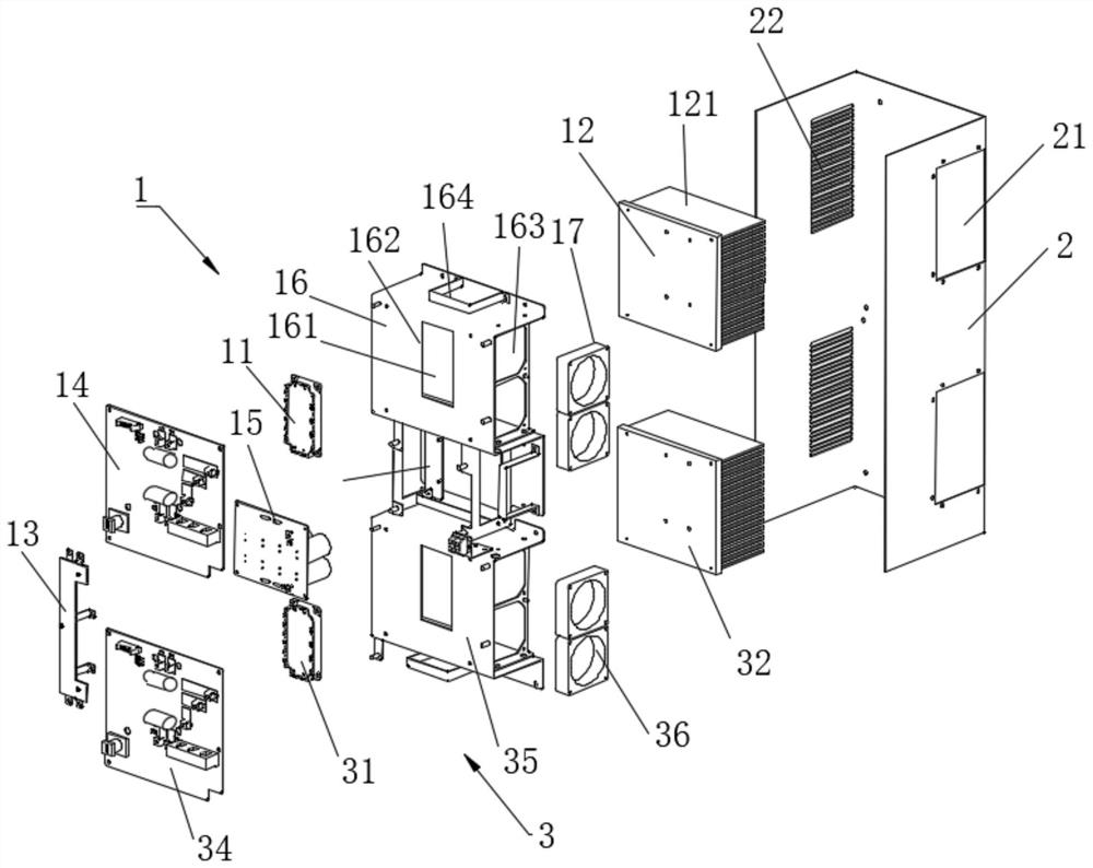
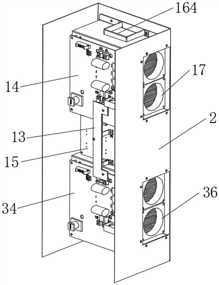
[0032] Embodiment 2, with reference to figure 2Specifically, in the solution of this embodiment, a heat dissipation structure for multiple frequency converter groups includes the control cabinet body 2 and multiple groups of frequency converter groups; each of the frequency converter groups moves from bottom to top or Vertically arranged and installed inside the control cabinet body 2 from top to bottom; the second group of frequency converters 3 also includes: heating element power modules 31, radiators 32, copper bars, drive electronic boards 34, fixed sheet metal Part 35 and heat dissipation fan 36; through the integrated design of the heat dissipation air duct and the control cabinet body 2, the heat dissipation between two or more frequency converter groups does not affect each other. It should be noted that the heat dissipation between two or more inverter groups does not affect each other, the volume of the control cabinet body 2 or the volume of the inverter group is ...


PUM


Abstract

The invention discloses a heat dissipation structure of a frequency converter group or multiple frequency converter groups. The heat dissipation structure comprises the frequency converter groups anda control cabinet body. The frequency converter group comprises a heating element power module, a radiator, a copper bar, a driving electronic board, a bus capacitor board, a fixed sheet metal part and a cooling fan. The fixed sheet metal part is installed in the control cabinet body. The fixed sheet metal part is provided with a placing part for accommodating a radiator; a rectangular through hole is formed in the bottom of the placing part; one surface of the heating element power module penetrates through the rectangular through hole and is in surface contact with the end surface of the radiator, and the other surface of the heating element power module is electrically connected with the driving electronic board; a heat dissipation part is arranged on the side surface of the fixed sheetmetal part; the heat dissipation fan is mounted on the heat dissipation part; the control cabinet body is provided with a heat dissipation port corresponding to the heat dissipation part. Through theintegrated design of the heat dissipation air duct and the control cabinet body, the frequency converter group realizes heat dissipation in the horizontal direction; and when multiple frequency converter groups are arranged, the heat dissipation among the frequency converter groups is not influenced.

Description

technical field [0001] The invention relates to the technical field of heat dissipation of elevator frequency converters, in particular to a heat dissipation structure of a frequency converter group or a multi-frequency converter group. Background technique [0002] The elevator control cabinet is the control center of the elevator. There are many heating devices inside, and the frequency converter is the most prominent. The usual design technique is to set the inverter on the top of the control cabinet, and use the exhaust device to discharge the heat of the inverter vertically out of the cabinet. However, if the control cabinet needs to arrange multiple frequency converter groups, they are usually arranged side by side, resulting in an increase in the width or thickness of the control cabinet, so that the entire elevator control cabinet has a large volume and increases the cost. For machine room-less elevators and small machine room elevators, the size of the control cabi...

Claims


Application Information

Patent Timeline
Patent Type & Authority Applications(China)
IPC IPC(8): H05K7/20H05K7/02H05K5/02H02M1/00
CPCH02M1/00H05K5/0213H05K5/0217H05K7/02H05K7/20145H05K7/20172H05K7/2039H05K7/20909
Inventor 何展荣郭威苏文圣何智杰何小楣
Owner HITACHI ELEVATOR CHINA
Why Eureka
Try Eureka