Mower with independent heat dissipation air duct

A heat dissipation air duct and lawn mower technology, which is applied to harvesters, cutters, agricultural machinery and implements, etc., can solve the problems of unreasonable location of motor heat dissipation vents, easy entry of water mist, easy entry of grass dust, etc. , to achieve the effect of reducing dust entering the motor, compact structure, and speeding up the air flow

Active Publication Date: 2021-04-02
ZHEJIANG YAT ELECTRICAL APPLIANCE CO LTD
View PDF6 Cites 2 Cited by
  • Summary
  • Abstract
  • Description
  • Claims
  • Application Information

AI Technical Summary

Problems solved by technology

[0003] The purpose of the present invention is to provide a lawn mower with an independent heat dissipation air duct, which can effectively solve the problems in the prior art that the location of the motor heat dissipation vent is unreasonable, which leads to easy entry of grass dust during work or easy entry of water mist during cleaning.

Method used


Image

  • Mower with independent heat dissipation air duct
  • Mower with independent heat dissipation air duct
  • Mower with independent heat dissipation air duct

Examples


Embodiment 1

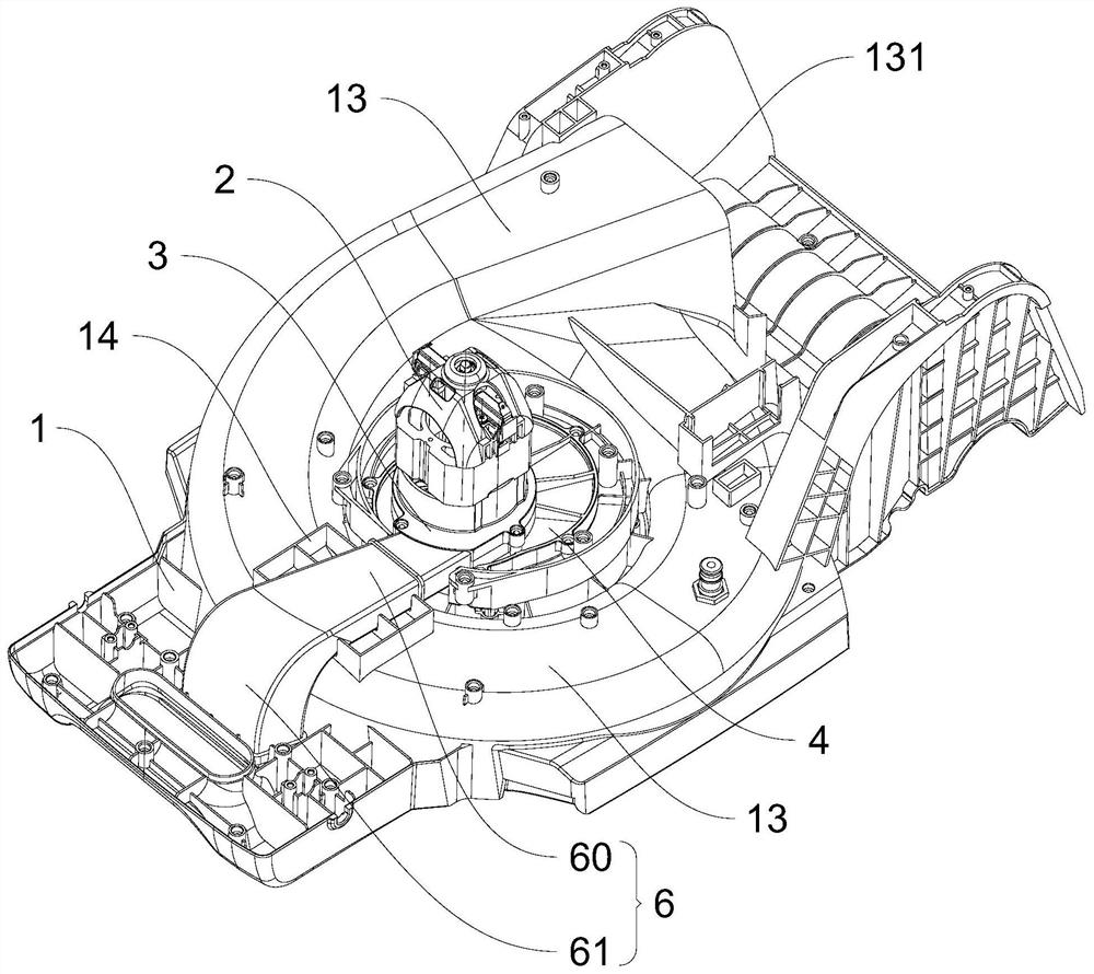
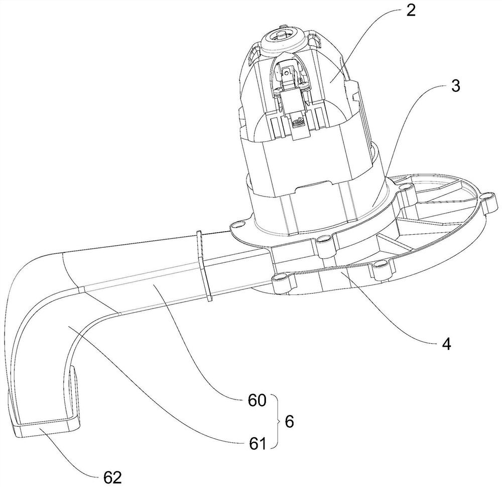
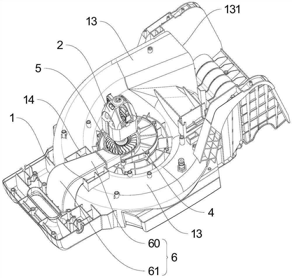
[0025] Embodiment one: if figure 1 As shown, the lawn mower with independent heat dissipation air duct provided by this embodiment includes a chassis 1, a motor 2, a motor base 3 and a motor support plate 4, and a volute 13 is arranged on the chassis 1, and the volute 13 surrounds the motor support plate 4 are arranged in a circle, the volute 13 mentioned here refers to the annular raised part on the chassis 1, that is, the volute 13 and the chassis 1 are integrally formed, because it is shaped like a snail shell, it is called a volute 13. combine figure 2 As shown, the motor 2 is installed on the motor base 3, the motor base 3 is connected to the motor support plate 4, the motor support plate 4 is connected to the chassis 1, and the motor 2 is fixedly supported on the chassis 1 by the motor base 3 and the motor support plate 4. combine image 3 and Figure 4 As shown, the middle part of the output shaft of the motor 2 is provided with a cooling vane 5, the motor base 3 a...

Embodiment 2

[0032] Embodiment two: if Figure 6 and Figure 7 As shown, the difference between this embodiment and the above-mentioned embodiments is that the lawn mower with independent heat dissipation air duct provided by this embodiment is also provided with a first air guide vane 11 in the air outlet 10, and the first air guide vane 11 One end of one end is flush with the edge of the air outlet 10 or stretches out the air outlet 10, and the surface of the chassis 1 between the grass collecting passage 130 and the air outlet 10 is provided with an air supply slot 15, and the first air guide vane 11 is connected with the air supply. The groove 15 is used to make part of the cooling air flow into the grass collecting channel 130 .

[0033] Based on the above-mentioned distinguishing technical features, in this embodiment, by setting up the air supply groove 15 on the chassis 1 between the air outlet 10 and the grass collection channel 130, and cooperating with the first air guide vane ...


PUM


Abstract

The invention discloses a mower with an independent heat dissipation air duct. The mower comprises a chassis, a motor, a motor base and a motor supporting plate, a volute is arranged on the chassis, ablade is fixedly connected to the end of an output shaft of the motor, the motor base and the motor supporting plate are connected up and down to form a containing cavity, the mower further comprisesthe heat dissipation air duct, and an air inlet of the heat dissipation air duct is connected with the containing cavity in a sealed manner. An air outlet of the heat dissipation air duct is led to the outer side of the volute and faces downwards. The independent heat dissipation air duct is arranged for the motor, the open structure of the air duct in the prior art is changed, grass cuttings anddust cannot enter the motor along the heat dissipation air duct when the mower works, meanwhile, the air outlet is formed at the outer side of the volute, the volute is avoided, when the volute is cleaned, water mist cannot enter the motor along the air outlet, damage to the motor is avoided, the cross sectional area of the heat dissipation air duct is gradually increased in the airflow flowing direction, and the heat dissipation efficiency can be improved.

Description

technical field [0001] The invention belongs to the field of garden equipment, in particular to a lawn mower with an independent heat dissipation air duct. Background technique [0002] The lawn mower is a common garden equipment. The motor drives the blade to rotate to cut the lawn. The chassis is also designed with a volute. Flow into the grass collection box. Because the motor will generate heat when it runs for a long time, the output shaft of the motor is provided with fan blades, so that when the motor drives the blade to rotate, it will also drive the fan blades to rotate, thereby cooling the motor. In the prior art, an open air duct is generally used, that is, a vent is set under the motor support plate, so that the grass dust is easy to enter the motor, and it is easy to cause damage to the motor after a period of use, and some lawn mowers set the vent It is located at the back of the motor support plate, which can reduce the entry of grass dust into the motor to ...

Claims


Application Information

Patent Timeline
Patent Type & Authority Applications(China)
IPC IPC(8): A01D43/077A01D75/00
CPCA01D43/077A01D75/00
Inventor 邹斌张闯陈刚
Owner ZHEJIANG YAT ELECTRICAL APPLIANCE CO LTD
Why Eureka
Try Eureka