A fast dust removal device for flat lens processing
A lens processing and dust removal device technology, applied in cleaning methods and tools, cleaning methods using tools, chemical instruments and methods, etc., can solve the problems of troublesome processing of flat lenses, resource consumption, and heavy workload, and achieve saving resources, reduce labor intensity, and improve efficiency
- Summary
- Abstract
- Description
- Claims
- Application Information
AI Technical Summary
Problems solved by technology
Method used
Image
Examples
Embodiment 1
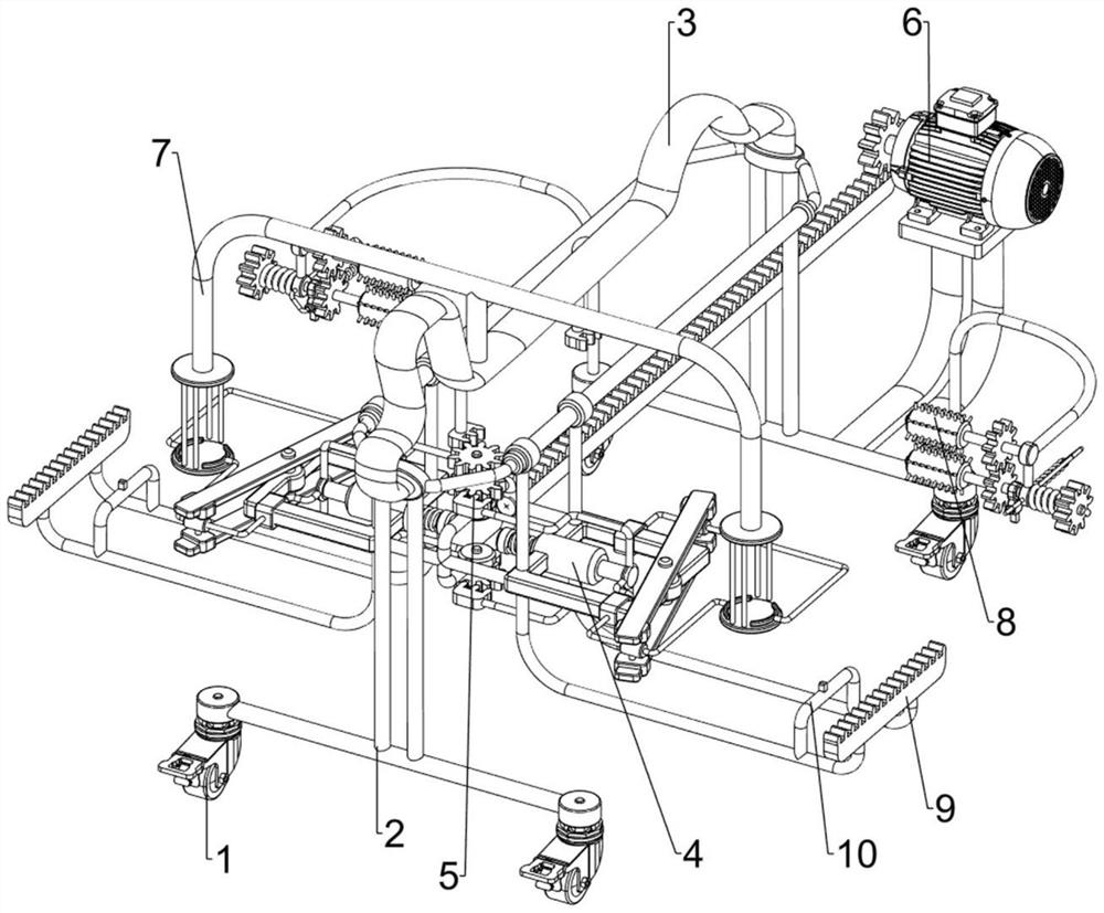
[0072] A fast dust removal device for flat lens processing, such as figure 1 As shown, it includes a caster 1, a first support frame 2, a second support frame 3, a clamping mechanism 4 and a rotation mechanism 5, and the first support frame 2 is arranged on the front and rear sides of the second support frame 3, and the two first support frames Both left and right sides of the support frame 2 are equipped with casters 1 , the bottom of the second support frame 3 is provided with a clamping mechanism 4 , and a rotation mechanism 5 is provided between the second support frame 3 and the clamping mechanism 4 .
[0073] When people need to remove dust from the flat lens, people place the flat lens in the middle of the clamping mechanism 4, and then manually push the clamping mechanism 4 to move to the rear side, so that the rotating mechanism 5 moves the clamping mechanism 4, and then makes The clamping mechanism 4 clamps the flat lens so that people can remove dust from the flat l...
Embodiment 2
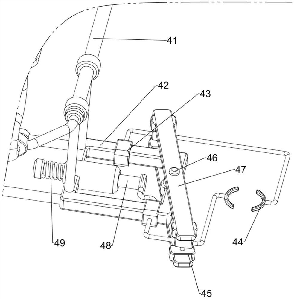
[0075] On the basis of Example 1, such as figure 2 As shown, the clamping mechanism 4 includes a first slide rail 41, a third support frame 42, a first slide block 43, a clamp 44, a second slide block 45, a first rotating shaft 46, a second slide rail 47, a third slide Block 48 and the first spring 49, the first slide rail 41 is arranged symmetrically between the front and rear sides of the second support frame 3 outer walls, and the third support frame 42 is provided slidingly between the two first slide rails 41. The support frame 42 is equipped with a first slide block 43 in front, rear, left, and right symmetrical slides, four first slide blocks 43 outsides are connected with clamps 44, four clamps 44 are equipped with a second slide block 45, a third support frame 42 Both left and right sides are rotatably provided with a first rotating shaft 46, and the upper and lower sides of the two first rotating shafts 46 are provided with second slide rails 47, and the two second ...
Embodiment 3
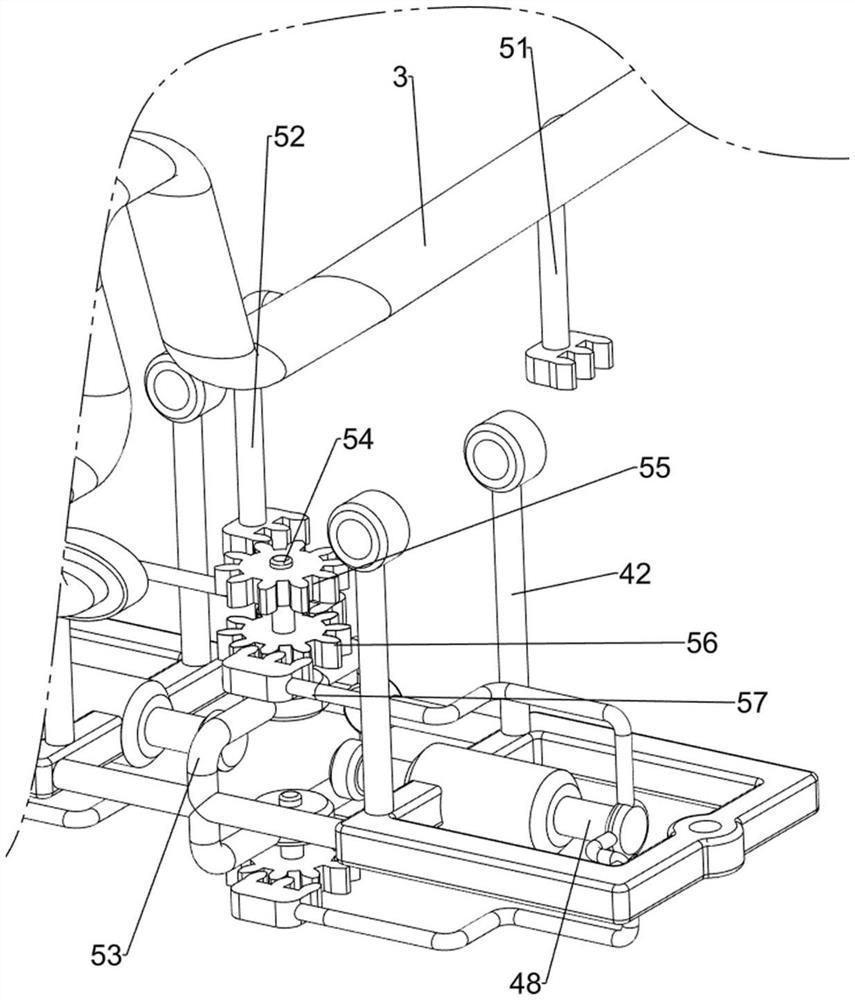
[0078] On the basis of Example 2, such as figure 1 , image 3 , Figure 4 , Figure 5 , Image 6 , Figure 7 , Figure 8 and Figure 9 As shown, the rotating mechanism 5 includes a first rack 51, a second rack 52, a fourth support frame 53, a second rotating shaft 54, a first gear 55, a second gear 56 and a third rack 57, and the second support The left side of the frame 3 middle part is provided with the first rack 51, the left part of the second support frame 3 front side is provided with the second rack 52, and the third support frame 42 middle part is provided with the fourth support frame 53 up and down both sides, two The outside of the fourth support frame 53 is equipped with a second rotating shaft 54 in a rotating manner, and the second rotating shaft 54 on the upper side is provided with a first gear 55, and the first gear 55 meshes with the second rack 52 and the first rack 51. A second gear 56 is provided in the middle of each second rotating shaft 54 ...
PUM
 Abstract
Description
Claims
Application Information
 - R&D
- Intellectual Property
- Life Sciences
- Materials
- Tech Scout
- Unparalleled Data Quality
- Higher Quality Content
- 60% Fewer Hallucinations
Browse by: Latest US Patents, China's latest patents, Technical Efficacy Thesaurus, Application Domain, Technology Topic, Popular Technical Reports.
© 2025 PatSnap. All rights reserved.Legal|Privacy policy|Modern Slavery Act Transparency Statement|Sitemap|About US| Contact US: help@patsnap.com


