Process for increasing shearing length of cold-rolled circle shear

A technology of disc shears and discs, which is applied in the direction of shearing devices, metal processing equipment, shearing machine accessories, etc., can solve the problems of accelerated wear, prone to chipping, mild wear and off-line problems, etc., to achieve extended The effect of cutting distance, improving production efficiency and reducing cost

Pending Publication Date: 2021-04-02
天津市新天钢冷轧薄板有限公司
View PDF0 Cites 0 Cited by
  • Summary
  • Abstract
  • Description
  • Claims
  • Application Information

AI Technical Summary

Problems solved by technology

The raw materials for continuous pickling and cold rolling units, push-pull pickling and other units are all raw materials in the hot rolling state. There are two main directions of perfecting the internal quality, which leads to the occurrence of problems such as the disc scissors are easy to break, mildly worn off the assembly line, etc., which undoubtedly increases the cost of the trimming process
[0003] To sum up, it is difficult for the GAP-LAP interlocking disc shears widely used at present to overcome the problems of chipping and mild wear off the production line:
[0004] (1) Since the steel strength range corresponding to the GAP-LAP adjustment curve is fixed, when the local performance of the shear material is unstable or the steel grade exceeds the limit range, it is easy to break the knife;
[0005] (2) GAP-LAP interlocking disc shears, when the scissors are slightly worn, in principle, the GAP-LAP value can be moderately adjusted to slow down the wear rate, but because the actual wear degree is unpredictable, the results after fine-tuning often appear Cases of accelerated wear
[0006] (3) The market's perfect requirements for edge quality directly reduce the cutting distance of the disc shears, and it needs to be off-line under mild wear and tear

Method used


Image

  • Process for increasing shearing length of cold-rolled circle shear
  • Process for increasing shearing length of cold-rolled circle shear

Examples


Embodiment Construction

[0022] It should be noted that, in the case of no conflict, the embodiments of the present invention and the features in the embodiments can be combined with each other.

[0023] In describing the present invention, it should be understood that the terms "center", "longitudinal", "transverse", "upper", "lower", "front", "rear", "left", "right", The orientations or positional relationships indicated by "vertical", "horizontal", "top", "bottom", "inner", "outer", etc. are based on the orientation or positional relationships shown in the drawings, and are only for the convenience of describing the present invention Creation and simplification of description, rather than indicating or implying that the device or element referred to must have a specific orientation, be constructed and operate in a specific orientation, and therefore should not be construed as limiting the invention. In addition, the terms "first", "second", etc. are used for descriptive purposes only, and should no...


PUM


Abstract

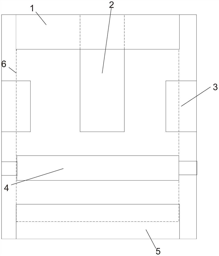
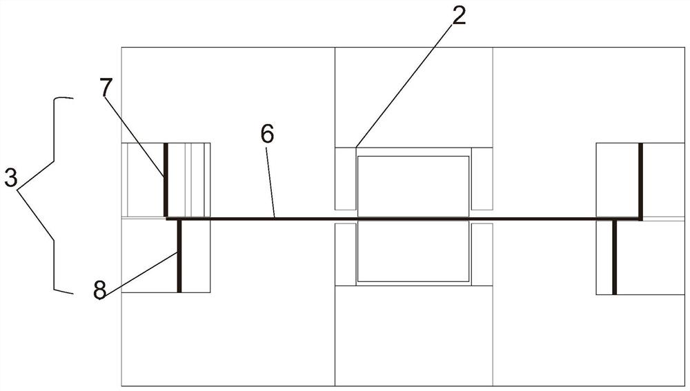
The invention provides a process for increasing the shearing length of a cold-rolled circle shear. The process comprises the steps of shear material selection and mixed assembly and use of upper and lower shear different hardness, a first loop, pressing rollers, circle shear mechanisms, a driving roller mechanism and a second loop are included, the first loop and the second loop can be sleeved with strip steel, the strip steel is distributed between the first loop and the second loop, the strip steel makes contact with the two pressing rollers up and down and is connected with the two pressingrollers, the circle shear mechanisms are symmetrically arranged on the left side and the right side of the strip steel and comprise an upper circle shear and a lower circle shear, the upper circle shear and the lower circle shear are made of different materials, the upper circle shear is made of 7CrMo3V2Si, the lower circle shear is made of W6Mo5Cr4V2, and 0.5 mm is reserved in the later period of machining of the upper circle shear and the lower circle shear for ultra-fine grinding treatment. The shearing distance of the circle shear is prolonged, the occurrence of cutter breakage is reduced, the production efficiency of a cold rolling unit can be improved, and the input cost of the circle shear is reduced.

Description

technical field [0001] The invention belongs to the field of cold rolling technology, and in particular relates to a technology for increasing the shear length of cold rolling disc shears. Background technique [0002] At present, in the process of cold rolling and cold rolling, disc shears have been widely used as key equipment for removing edge defects of strip steel and ensuring width accuracy. The raw materials for continuous pickling and cold rolling units, push-pull pickling and other units are all raw materials in the hot rolling state. There are two main directions of perfecting the internal quality, which leads to the occurrence of problems such as the disc scissors are easy to break and mildly worn off the assembly line, which undoubtedly increases the cost of the trimming process. [0003] To sum up, it is difficult for the GAP-LAP interlocking disc shears widely used at present to overcome the problems of chipping and mild wear off the production line: [0004]...

Claims


Application Information

Patent Timeline
Patent Type & Authority Applications(China)
IPC IPC(8): B23D19/06B23D33/02B21B15/00
CPCB21B15/00B21B15/0007B23D19/06B23D33/02
Inventor 姬更岐
Owner 天津市新天钢冷轧薄板有限公司
Why Eureka
Try Eureka