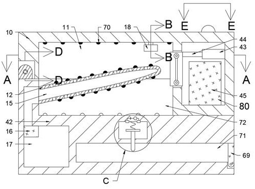
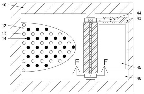
[0025] Combine below Figure 1-9 The present invention is described in detail, wherein, for the convenience of description, the orientations mentioned below are defined as follows: figure 1 The up, down, left, right, front and back directions of the projection relationship itself are the same.
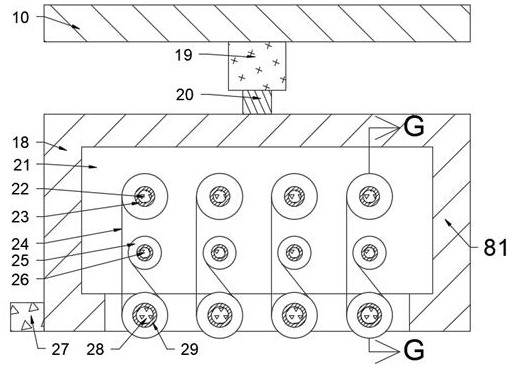
[0026] combined with Figure 1-9 Described a kind of portable mouth mask sterilizing storage device, comprises upper placement block 10, and described upper placement block 10 is provided with the upper placement chamber 11 of opening downward, and described upper placement chamber 11 right side is provided with crushing mechanism 80, so The crushing mechanism 80 is used to crush the mask after repeated use;
[0027] A marking hydraulic cylinder 19 is fixed on the upper inner wall of the upper placement chamber 11, and a marking hydraulic rod 20 is controlled inside the marking hydraulic cylinder 19, and a marking block 18 is fixed on the lower end of the marking hydraulic rod 20. , the marking block 18 is provided with a marking cavity 21 with an opening downward, and four marking mechanisms 81 are arranged in the marking cavity 21, and the marking mechanism 81 is included in front of the marking cavity 21. The side inner wall is rotated with a first rotating shaft 22, and the first rotating shaft 22 is fixed with a first reel 23. The rear side of the marking chamber 21 is provided with a first transmission chamber 30, and the rear of the first transmission chamber 30 is The side inner wall is fixedly provided with a marking motor 32, and the marking motor 32 is fixedly connected with the first rotating shaft 22, and the first rotating shaft 22 is fixedly provided with a first gear 31, and the first gear 31 is connected with the second The gears 33 are meshed and connected. The second gear 33 is fixed with a second shaft 26. The second shaft 26 is fixed with a second reel 25. The inner wall of the front side of the marking chamber 21 is rotated with a third shaft. Rotating shaft 28, the third rotating shaft 28 is fixedly provided with a pressure marking wheel 29, and the left end face of the marking block 18 is fixedly provided with an identification block 27, and the identification block 27 is used to identify the disinfection times of the mask;
[0028] The upper placement block 10 is rotationally connected with the lower placement block 42 through the fourth rotating shaft 67, and the front end of the fourth rotating shaft 67 is fixedly provided with a switch motor 66, and the switching motor 66 is fixedly arranged in the lower placement block 42 , the lower placement block 42 is provided with a spare detection mechanism 82, and the spare detection mechanism 82 includes a downwardly opening wiring cavity 41 fixedly provided in the lower placement block 42, and the inner wall of the upper side of the wiring cavity 41 A first energization block 36 and a second energization block 37 are fixedly arranged, and the first energization block 36 and the second energization block 37 are connected by wires, and a power supply 34 and an induction block 35 are also connected in series on the wires. A compression spring 38 is fixed on the inner wall of the upper side of the wiring chamber 41, and a third power supply block 39 is fixed on the lower end surface of the compression spring 38, and a contact rod 40 is fixed on the lower end surface of the third power supply block 39, and the contact rod 40 Used to contact and detect whether a spare mask is available.
[0029]Beneficially, the crushing mechanism 80 includes a crushing chamber 46 with an opening facing left on the inner wall on the right side of the upper placement chamber 11, and a crushing chamber 45 is fixedly provided on the inner wall of the lower side of the crushing chamber 46, and the crushing chamber 46 The inner wall of the right side is fixedly provided with a telescopic hydraulic cylinder 43, and a telescopic hydraulic rod 44 is controlled in the telescopic hydraulic cylinder 43. The first chute 47 with the opening facing backward, the inner wall of the lower side of the first chute 47 is embedded with a stepping motor 52, and the upper end surface of the stepping motor 52 is fixedly provided with a first screw rod 50, and the first wire The upper end surface of the rod 50 is fixedly provided with a second screw rod 49, the first screw rod 50 is threaded with a first slider 51, the second screw rod 49 is screwed with a second slider 48, and the clamp A second chute 53 with an opening forward is provided in the block 73, and a slide bar 54 is fixedly provided on the inner wall of the upper side of the second chute 53, and a third slide block 55 and a fourth slide bar 54 are slidably provided on the slide bar 54 Slider 59, the front end of the third slider 55 is embedded with a drive motor 56, the front end of the drive motor 56 is fixed with a fifth rotating shaft 57, and the fifth rotating shaft 57 is fixed with a first rubber wheel 58 , the front end surface of the fifth rotating shaft 57 is rotatably connected with the rear end surface of the second slider 48, the rear end surface of the fourth slider 59 is fixedly provided with a fixed shaft 61, and the fixed shaft 61 is rotatably provided with a second rubber The wheel 60 and the front end of the fixed shaft 61 are fixedly connected with the first sliding block 51 .
[0030] Beneficially, the lower placement block 42 is provided with a lower placement cavity 72 with an upward opening, and the lower inner wall of the lower placement cavity 72 and the upper inner wall of the upper placement cavity 11 are respectively fixed with N ultraviolet lamp beads 70, At the same time, a hygroscopic support 12 is fixed on the inner wall on the left side of the lower placement cavity 72, the upper and lower end surfaces of the hygroscopic support 12 are fixed with the ultraviolet lamp beads 70, and the lower placement block 42 is provided with a hygroscopic channel 15. The moisture absorption channel 15 communicates with the water collection chamber 17, and the upper inner wall of the water collection chamber 17 is fixed with a dehumidification pump 16.
[0031] Beneficially, a paper strip 24 is wound on the first winding wheel 23, and the paper strip 24 passes around the marking wheel 29 and is wound on the second winding wheel 25, and the paper strip 24 The corresponding signal identification patch is pasted.
[0032] Beneficially, the lower placement block 42 is provided with a spare mask cavity 71 opening to the right, and a baffle plate 69 is provided on the right side inner wall of the spare mask cavity 71 .
[0033] Beneficially, a first indicator light 62 , a second indicator light 63 , a third indicator light 64 , and a fourth indicator light 65 are fixedly provided on the upper end surface of the upper placement block 10 .
[0034] Beneficially, the third energization block 39 can communicate with the circuit after contacting the first energization block 36 and the second energization block 37 .
[0035] Instructions
[0036] In the initial state, the compression spring 38 is in a normal state.
[0037] Manually take off the mask, switch motor 66 starts, switch motor 66 controls the upper placement block 10 to rotate and open, put the mask into the upper placement cavity 11, make the side of the mask close to the lip fit the outer surface of the moisture absorption bracket 12, and switch The motor 66 starts to reverse, and the switch motor 66 drives the upper placement block 10 to reset.
[0038] Firstly, the mask is sterilized, and the ultraviolet lamp bead 70 lights up, and the ultraviolet lamp bead 70 performs ultraviolet disinfection on the inner and outer surfaces of the mask, and the dehumidification pump 16 is started at the same time as the disinfection, and the dehumidification pump 16 sucks the condensed water vapor inside the mask through the moisture absorption channel 15 into the water collection It is stored in the cavity 17, and the first indicator light 62 lights up after the disinfection is completed.
[0039] After the disinfection is completed, the mask will be identified and marked, and the recognition block 27 will start to judge whether there is a number of marks on the mask. If the mask is used for the first time and is disinfected for the first time, if there is no mark on the surface of the mask, then start the corresponding The marking motor 32, the marking motor 32 controls the first rotating shaft 22 to rotate, the first rotating shaft 22 drives the first reel 23 to rotate, the first rotating shaft 22 drives the first gear 31 to rotate, and the first gear 31 drives the second gear 33 to rotate , the second gear 33 drives the second rotating shaft 26 to rotate, and the second rotating shaft 26 drives the second reel 25 to rotate, and the logo on the second reel 25 is printed on the outer surface of the mask.
[0040] If there is a frequency mark on the mask, when the mark shows that the number of times of disinfection is 2-3 times, the second indicator light 63 lights up, indicating that the mask has been reused for 2-3 times, and a new mask should be replaced in time, and continue to start the relevant The corresponding marking motor 32, the marking motor 32 controls the rotation of the first rotating shaft 22, the first rotating shaft 22 drives the first scroll wheel 23 to rotate, the first rotating shaft 22 drives the first gear 31 to rotate, and the first gear 31 drives the second gear 33 Rotate, the second gear 33 drives the second rotating shaft 26 to rotate, and the second rotating shaft 26 drives the second scroll wheel 25 to rotate, and the mark of the disinfection frequency is printed on the outer surface of the mask.
[0041] When the sign shows that it has been sterilized 4 times, the standby detection mechanism is started, and the power supply 34 is energized to detect whether there is a spare mask in the spare mask cavity 71. If the baffle plate 69 is opened in advance, a piece of spare mask is put into the spare mask cavity 71. The mask pushes the contact rod 40 up, the contact rod 40 drives the third energization block 39 to move upward, the compression spring 38 is compressed, the third energization block 39 contacts the first energization block 36 and the second energization block 37 and conducts the circuit, the induction block 35 Sends a signal that can start smashing masks.
[0042] The telescopic hydraulic cylinder 43 controls the extension of the internal telescopic hydraulic rod 44, the telescopic hydraulic rod 44 drives the clamping block 73 to stretch out to the left, the stepper motor 52 starts, the stepper motor 52 drives the first screw mandrel 50 to rotate, and the first screw mandrel 50 Drive the second screw mandrel 49 to rotate, the first screw mandrel 50 and the second screw mandrel 49 drive the first slider 51 and the second slider 48 to move towards each other, clamp some areas of the mask, and drive the motor 56 at the same time Start, the drive motor 56 controls the fifth rotating shaft 57 to rotate, the fifth rotating shaft 57 drives the first rubber wheel 58 to rotate, the first rubber wheel 58 and the second rubber wheel 60 enter the crushing chamber 46 by driving the mask, and the pulverizer 45 starts pulverizing, The mask is crushed and stored, and the third indicator light 64 lights up, indicating that the mask in the upper chamber 11 has been destroyed, and the spare mask is directly used.
[0043] If there is no spare mouth mask in the spare mouth mask chamber 71, then the fourth indicator light 65 lights up, indicating that the mouth mask must be changed quickly.
[0044] The above-mentioned embodiments are only to illustrate the technical concept and characteristics of the present invention, and the purpose is to enable those skilled in the art to understand and implement the present invention, and not to limit the protection scope of the present invention. All equivalent changes or modifications made according to the spirit of the present invention shall fall within the protection scope of the present invention.