Scaffold

A technology of scaffolding and support frame, applied in the field of scaffolding, can solve the problems of shaking safety, hidden dangers, workers prone to rollover when climbing, and achieve the effect of preventing rollover and increasing the degree of stability

Active Publication Date: 2021-04-02
YANTAI ENG & TECH COLLEGE YANTAI TECHNICIAN INST
View PDF7 Cites 3 Cited by
  • Summary
  • Abstract
  • Description
  • Claims
  • Application Information

AI Technical Summary

Problems solved by technology

[0004] In order to make up for the deficiencies of the prior art, the present invention proposes a scaffold, which is mainly used to solve the problem that when the scaffold is used on uneven ground, it will shake and cause potential safety hazards, and at the same time, it is prone to rollover when workers climb

Method used


Image

  • Scaffold
  • Scaffold
  • Scaffold

Examples


Embodiment 1

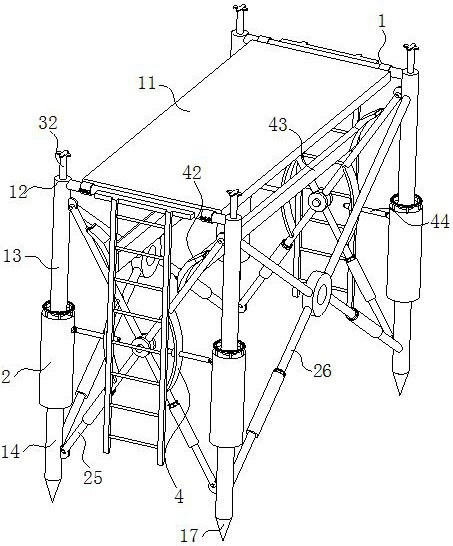
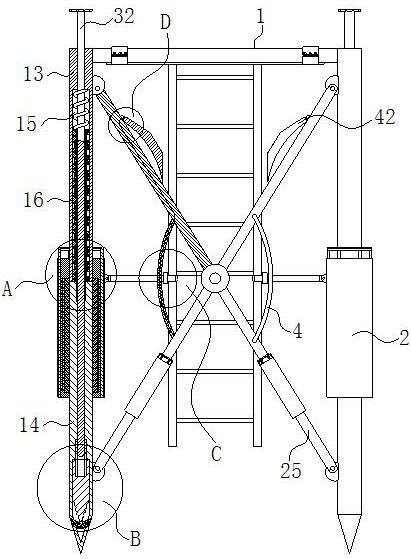
[0029] Example 1, such as Figure 1-Figure 6 Shown, a kind of scaffolding described in the present invention comprises support frame 1; The quantity of described support frame 1 is two and corresponds to each other; Both described support frames 1 are fixedly connected with struts; Two described support frames 1. On the opposite side of the supporting frame 1, a frame plate 11 is fixedly connected by bolts; the two supporting frames 1 include two supporting columns 12; each of the supporting columns 12 includes an upper column 13 and a lower column 14; the inner wall of each upper column 13 is provided with a first sliding groove 15, and the first sliding groove 15 communicates with the lower surface of the upper column 13; the upper surface of each lower column 14 is fixedly connected with a first sliding groove rod 16, and the first sliding rod 16 is slidably connected with the first chute 15; each of the first sliding rods 16 is connected with the first chute 15 by a spring...

Embodiment 2

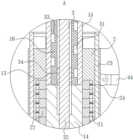
[0032] Example 2, such as Figure 1-Figure 6 As shown, a first helical groove 31 is provided in the inner wall of each of the first sliding rods 16, and the first helical groove 31 cooperates with the block 22; each of the inner walls of the first sliding rod 16 is provided with a The third chute 3, and the second slide bar 32 is slidably connected to the inner wall of the third chute 3, and the second slide bar 32 partly stretches out from the upper surface of the pillar 12; each of the third chute 3 inner walls There are evenly arranged first slots 33, and the first slots 33 partially extend into the inner wall of the lower column 14; the outer surface of each of the second sliding rods 32 is fixed with evenly arranged first side plates 34, and The first side plate 34 cooperates with the first slot 33;

[0033] When working, because the first helical groove 31 and the block 22 cooperate with each other, after the adjustment of the support column 12 is completed, part of the...

Embodiment 3

[0034] Example 3, such as Figure 1-Figure 6 As shown, each of the second sliding rods 32 extends into the inner wall of the lower column 14 and is slidably connected with the lower column 14; a tapered groove is provided in the inner wall of the tapered column 17 below each of the second sliding rods 32 35; each of the tapered grooves 35 is slidably connected with a tapered block 36, and the outer surface of the tapered block 36 is provided with a second thread groove 37; each of the tapered blocks 36 inner walls are provided with a cross Groove 38; the top of each cross groove 38 is fixedly connected with the second side plate 39 uniformly arranged on the outer surface of the second slide bar 32, and the second side plate 39 cooperates with the cross groove 38; each of the cones Evenly arranged insertion rods 391 are slidably connected to the inner wall of the cone column 17 below the shape block 36, and the insertion rods 391 are all matched with the second threaded groove ...


PUM


Abstract

The invention belongs to the technical field of building tools, and particularly relates to a scaffold. The scaffold comprises two supporting frames which correspond to each other, wherein supportingrods are fixedly connected to the two supporting frames; frame plates are fixedly connected to the supporting rods of the supporting frames on the opposite sides of the two supporting frames through bolts; each supporting frame comprises two supporting columns; each supporting column comprises an upper column and a lower column; a first sliding groove is formed in the inner wall of each upper column; and a first sliding rod is fixedly connected to the upper surface of each lower column. The scaffold is mainly used for solving the problems that when a wall is built at present, the used scaffoldshakes when being installed on the uneven ground, although building workers can use bricks for bedding, potential safety hazards generated by the shaking scaffold cannot be avoided, meanwhile, when the scaffold shakes, the building workers climb the scaffold, the scaffold is prone to rolling over, and therefore the potential safety hazards are increased.

Description

technical field [0001] The invention belongs to the technical field of construction tools, in particular to a scaffold. Background technique [0002] Scaffolding refers to the various supports set up on the construction site for workers to operate and solve vertical and horizontal transportation. According to the general terminology in the construction industry, scaffolding is used on the construction site for exterior walls, interior decoration, or places with high storey heights that cannot be directly constructed. It is mainly for construction workers to work up and down or for peripheral safety net enclosure and high-altitude installation components. Materials usually include: bamboo, wood, steel pipe or synthetic materials. Some projects also use scaffolding as a template. In addition, it is also widely used in the advertising industry, municipal administration, traffic roads and bridges, mines and other departments. However, there are still some problems with the curr...

Claims


Application Information

Patent Timeline
Patent Type & Authority Applications(China)
IPC IPC(8): E04G1/15E04G1/18E04G1/24
CPCE04G1/15E04G1/18E04G1/24
Inventor 孙学诗谭晓鹏王洋
Owner YANTAI ENG & TECH COLLEGE YANTAI TECHNICIAN INST
Why Eureka
Try Eureka