Wall building machine for building

A wall-laying machine and construction technology, applied in construction, building structure, processing of building materials, etc., can solve the problems of low work efficiency, high cost, complex structure, etc., to reduce labor intensity, low production cost, simple structure

Inactive Publication Date: 2021-04-02
泉州市元通科技服务有限公司
View PDF0 Cites 2 Cited by
  • Summary
  • Abstract
  • Description
  • Claims
  • Application Information

AI Technical Summary

Problems solved by technology

[0005] The purpose of the present invention is to provide a building wall-building machine that realizes automatic guidance and feeding to build walls, which is used to overcome the fact that most construction companies are still in the state of manual wall-building when making walls. This method is time-consuming and labor-intensive. The labor intensity is also very high, and the work efficiency is not high. Although a few foreign countries have developed automatic wall-building equipment or robots, due to their complex structure and high cost, they are still difficult to be widely used.

Method used


Image

  • Wall building machine for building
  • Wall building machine for building
  • Wall building machine for building

Examples


Embodiment 1

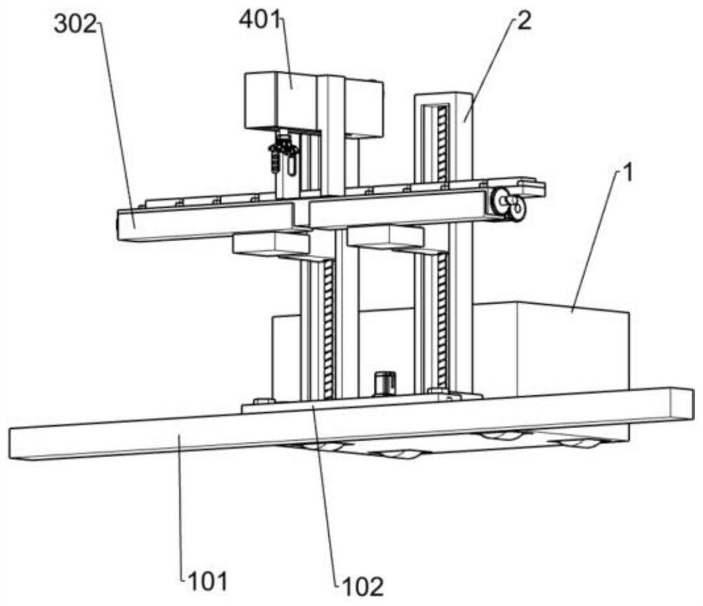
[0034] Such as Figure 1-Figure 7 Shown, a kind of construction wall-laying machine comprises slide box 1, slide rail 101, first fixed plate 201, first slide plate 102, lifting mechanism, reciprocating mechanism and feeding mechanism, and slide rail 101 is fixedly installed on slide box 1 The front side of the two first fixed plates 201 are fixedly installed on the lower side of the front part of the slide box 1, the rear side of the first slide plate 102 is fixedly connected with the front ends of the two first fixed plates 201, and the lower side of the first slide plate 102 is connected with the front end of the first fixed plate 201. Slide rail 101 is slidably connected, and two elevating mechanisms are fixedly installed in the front middle position of slide box 1, and reciprocating mechanism is threadedly connected with elevating mechanism, and the upper side of feeding mechanism is slidably connected with reciprocating mechanism.

[0035]When preparing for work, the work...

Embodiment 2

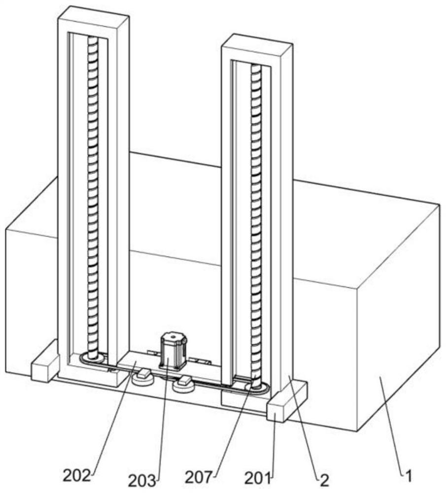
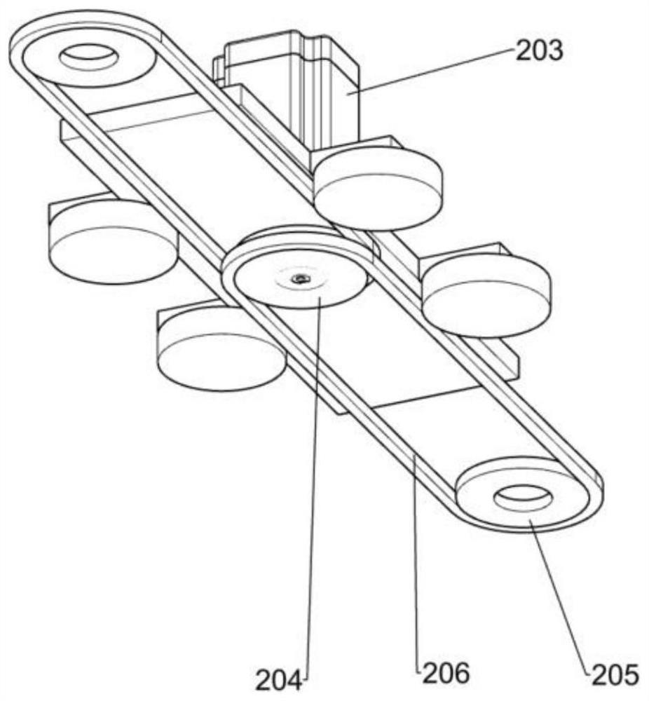
[0037] On the basis of Example 1, such as Figure 2-Figure 3 As shown, the lifting mechanism includes a first support frame 2, a connecting plate 202, a first motor 203, a first pulley 204, a second pulley 205, a belt 206 and a first screw rod 207, and the two first support frames 2 are fixed Installed on the lower side of the front middle of the slide box 1, the two first support frames 2 are located between the two first fixing plates 201, the connecting plate 202 is fixedly connected to the inside of the two first support frames 2, and the first motor 203 is fixedly installed on the upper middle position of the connecting plate 202, the output shaft of the first motor 203 runs through the upper and lower sides of the connecting plate 202, two first pulleys 204 are fixedly installed on the output shaft of the first motor 203, and the other four A first pulley 204 is rotatably installed on the front and rear sides of the connecting plate 202, two second pulleys 205 are respec...

Embodiment 3

[0040] On the basis of Example 2, such as Figure 4 As shown, the reciprocating mechanism includes a first slide frame 3, a stock plate 301, a second support frame 302, a second slide frame 303, a second motor 304, a first spur gear 305, a second screw rod 306, a second spur gear 307 and the first slide block 308, the rear sides of the two first slide frames 3 are threadedly connected with the two first screw rods 207 respectively, and the stock plate 301 is fixedly installed in the middle position of the upper side of the two first slide frames 3, the two A second support frame 302 is fixedly installed on the upper front sides of the two first slide frames 3 respectively, the second slide frame 303 is fixedly installed in the two second support frames 302, and the second motor 304 is fixedly installed on the right side of the first slide frame 3. On the rear side of the second support frame 302, the first spur gear 305 is fixedly installed on the output shaft of the second mo...


PUM


Abstract

The invention provides a wall building machine for a building. The wall building machine for the building comprises a sliding box, a sliding rail, first fixing plates, a first sliding plate, ascendingand descending mechanisms, a reciprocating mechanism and a feeding mechanism, wherein the sliding rail is fixedly arranged at one side of the sliding box; the two first fixing plates are fixedly arranged at the side, near the sliding rail, of the sliding box; one side of the first sliding plate is fixedly connected with the sides, far away from the sliding box, of the two first fixing plates; oneside of the first sliding plate is glidingly connected with the sliding rail; the two ascending and descending mechanisms are fixedly arranged at the side, near the sliding rail, of the sliding box;the reciprocating mechanism is in threaded connection with the ascending and descending mechanisms; and the feeding mechanism is glidingly connected with the side, far away from the sliding rail, of the reciprocating mechanism. The sliding rail is fixed; a walking building type wall building method is used, and a wall body is enabled to be tidy and straight in the wall building process; the feeding mechanism is used for replacing a manual brick conveying process, so that the labor intensity of workers is reduced, and the wall building efficiency is improved; and the wall building machine for the building is simple in structure and low in production cost.

Description

technical field [0001] The invention relates to a wall-laying machine, in particular to a wall-laying machine for construction. Background technique [0002] The existing wall-building process is to first clean the ground, find out the position to build the wall, pop up the ink line, and use a laser level to help confirm whether the line is vertical, so that the wall will not be skewed. The day before the wall is built, the brick The blocks should be poured with clean water to increase the adhesion to the cement mortar later. The ratio of cement to mortar is usually one to three when building walls. If the proportion of cement mortar is not appropriate, the wall structure will be unstable and problems will easily occur later. Even cracks, collapse, etc., on both sides of the head and tail of the wall, use a plumb or a laser level to fix the vertical nylon line with steel nails as a reference for the movement of the horizontal nylon line. The horizontal nylon line must be fix...

Claims


Application Information

Patent Timeline
Patent Type & Authority Applications(China)
IPC IPC(8): E04G21/22
CPCE04G21/22
Inventor 钟金菊
Owner 泉州市元通科技服务有限公司
Why Eureka
Try Eureka