Bidirectional buffer hydraulic cylinder

A two-way buffering, hydraulic cylinder technology, applied in the direction of fluid pressure actuating devices, can solve the problem of not installing two buffering devices, and achieve the effects of superior performance, improved buffering effect, and strong practicability

Active Publication Date: 2021-04-02
中国人民解放军96901部队24分队
View PDF9 Cites 1 Cited by
  • Summary
  • Abstract
  • Description
  • Claims
  • Application Information

AI Technical Summary

Problems solved by technology

Existing buffer devices can only achieve end buffering in one direction, and two buffer devices must be installed to achieve two-way buffering, but in some occasions there is no space for installing two buffer devices

Method used


Image

  • Bidirectional buffer hydraulic cylinder
  • Bidirectional buffer hydraulic cylinder

Examples


Embodiment Construction

[0030] The present invention will be described in detail below with reference to the accompanying drawings and examples.

[0031] This embodiment provides a two-way buffer hydraulic cylinder, which utilizes the orifice throttling feature to realize the buffer function of the piston rod 1 during the two-way process of extension and retraction, and can realize buffer functions under various load characteristics.

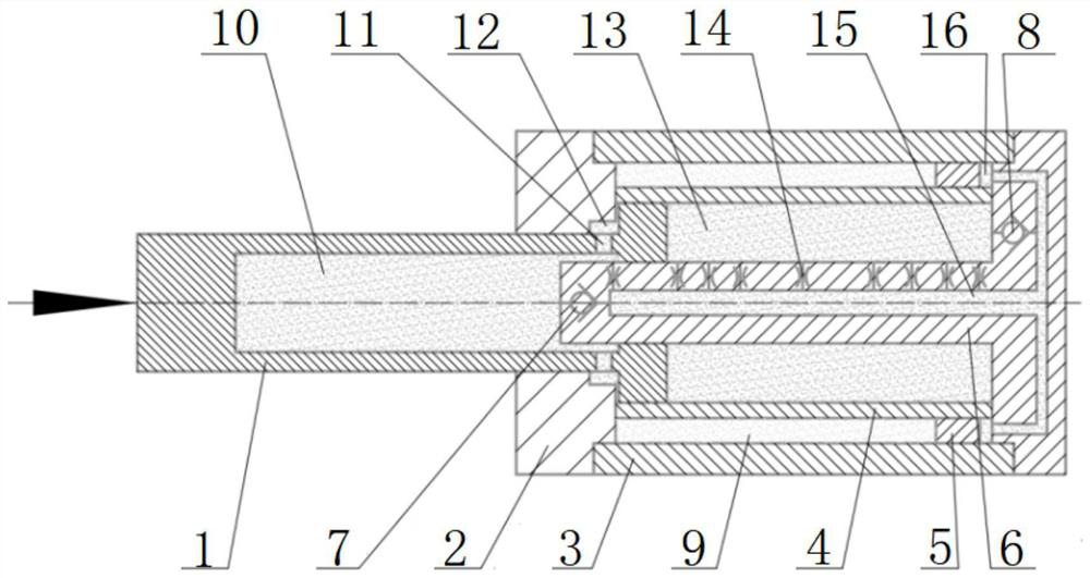
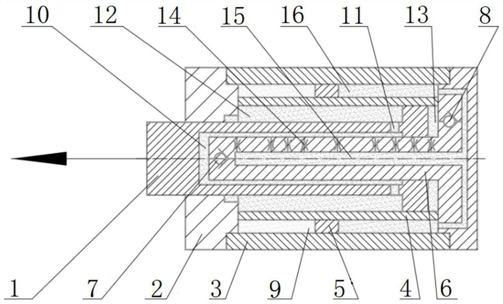
[0032] like figure 1 and 2 As shown, the two-way buffer hydraulic cylinder includes: piston rod 1, cylinder head 2, outer cylinder 3, inner cylinder 4, spacer sleeve 5, throttle rod 6, one-way valve A7 and one-way valve B8.

[0033] The connection relationship of the two-way buffer hydraulic cylinder is as follows: the throttle rod 6 is a hollow tube with an opening at one end and a hole at the other end, and its internal cavity is an oil chamber D15. It is fixedly connected with one end of the outer cylinder 3 to realize the coaxial assembly of the throttle rod 6 an...


PUM


Abstract

The invention discloses a bidirectional buffer hydraulic cylinder which comprises a piston rod, a cylinder body, a throttling rod and a one-way valve A. According to the bidirectional buffer hydrauliccylinder, a bidirectional buffer function under a variable load working condition is achieved by arranging the throttling rod inside, buffer brake control over the speed of a moving object in the bidirectional moving process can be achieved only through the structure of the bidirectional buffer hydraulic cylinder, and huge kinetic energy generated by rapid overturning or rapid stopping of high-speed reciprocating motion of a large-mass object can be absorbed immediately, so that the large-mass object is stopped gently; the cylinder body provided with a plurality of oil cavities is matched with the throttling rod provided with a plurality of throttling holes, so that a two-way buffering function of the piston rod in the telescopic process is achieved through the small hole throttling characteristic; and the bidirectional buffer hydraulic cylinder is compact in overall structure, excellent in performance, safe, reliable, high in practicability and particularly suitable for buffer braking of the high-speed large-mass moving objects with ultrahigh energy.

Description

technical field [0001] The invention relates to the technical field of fast turning or reciprocating motion start-stop of large-mass objects, in particular to a two-way buffer hydraulic cylinder. Background technique [0002] The function of the buffer hydraulic cylinder is to push and pull a reciprocating or overturning object, especially a large-mass and fast-moving object, to make it stop smoothly and slowly, and to protect the equipment from the strong impact of the object's motion energy. At present, the commonly used buffering methods of buffering hydraulic cylinders include variable cross-section type, annular gap flow type, buffering plunger type, multi-hole throttling type, etc., but the current buffering structure can only achieve single end buffering or piston retraction. One-way buffering. At present, there is no structure that can realize the two-way process buffering of moving objects only by its own structure; [0003] The large-mass object quickly flips and...

Claims


Application Information

Patent Timeline
Patent Type & Authority Applications(China)
IPC IPC(8): F15B15/14F15B15/20F15B15/22
CPCF15B15/1423F15B15/149F15B15/22
Inventor 杨必武孙建陈文学
Owner 中国人民解放军96901部队24分队
Why Eureka
Try Eureka