
Composite high-precision plate roller

A high-precision, composite technology, applied in mechanical roughness/irregularity measurement, measuring devices, instruments, etc., can solve the problems of high processing difficulty, poor processing quality, axis parallelism, and hollow cylindricity. Surface quality cannot be guaranteed To achieve the effect of improving the detection sensitivity and accuracy, and improving the positioning accuracy

Pending Publication Date: 2021-04-02
CHINA NON-FERROUS METALS PROCESSING TECH CO LTD
View PDF0 Cites 0 Cited by
  • Summary
  • Abstract
  • Description
  • Claims
  • Application Information

AI Technical Summary

Problems solved by technology

[0002] In the past, the plate-shaped roller used to detect the flatness of the surface of steel, copper, aluminum and other metal plates and strips has an integral structure. The axes of the rollers are evenly distributed, and run through the entire roller body along the axis of the plate-shaped roller. The circular hole for installing the sensor belongs to deep hole processing, which is difficult to process and poor in processing quality. The straightness of the hole and the parallelism of the axes between the holes , hollow cylindricity, and surface quality of the hole cannot be guaranteed; while the processing quality of the circular hole where the sensor is installed has a decisive impact on the detection sensitivity and accuracy of the flatness of the metal plate and strip. With the existing market The flatness requirements of metal plates and strips are getting higher and higher. The plate-shaped rollers with the overall structure in the past can no longer meet the current production and testing requirements of metal plates and strips. It has become an urgent technology in the field of metal plates and strips production and testing technology. obstacle

Method used


Image

  • Composite high-precision plate roller
  • Composite high-precision plate roller
  • Composite high-precision plate roller

Examples


Embodiment Construction

[0019] The present invention can be explained in detail through the following examples, and the purpose of disclosing the present invention is to protect all technical improvements within the scope of the present invention.

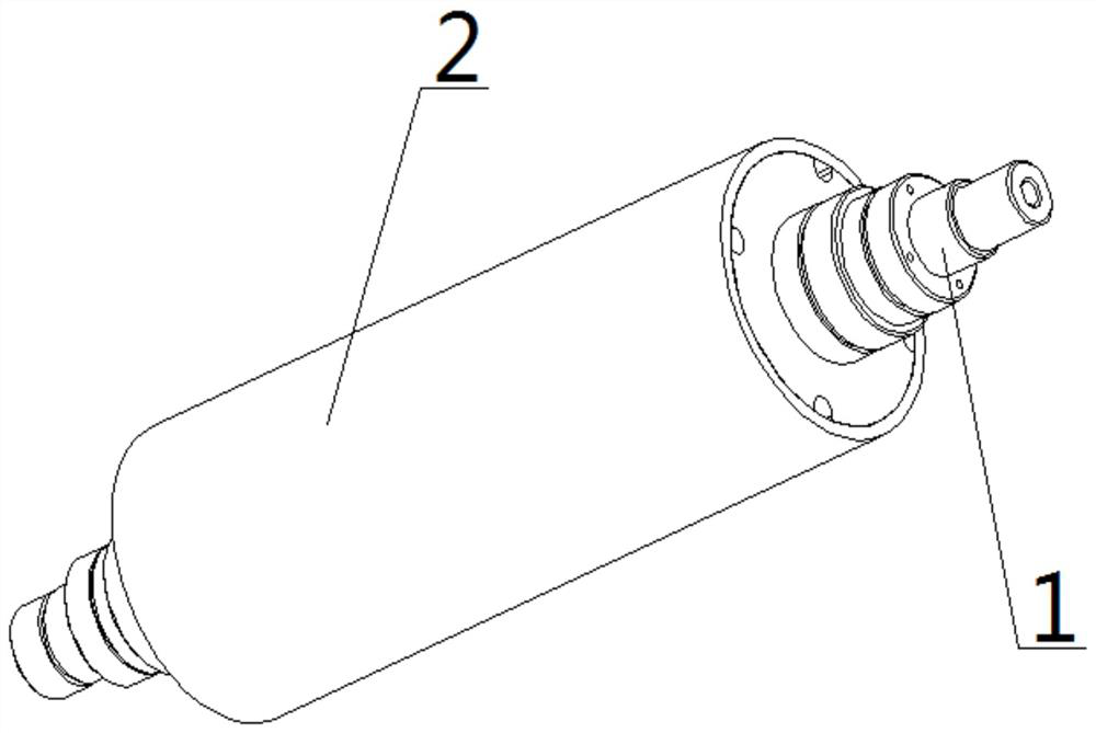
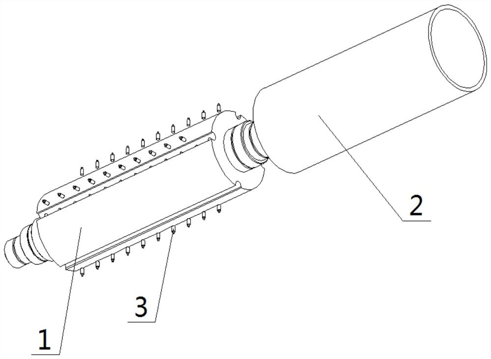
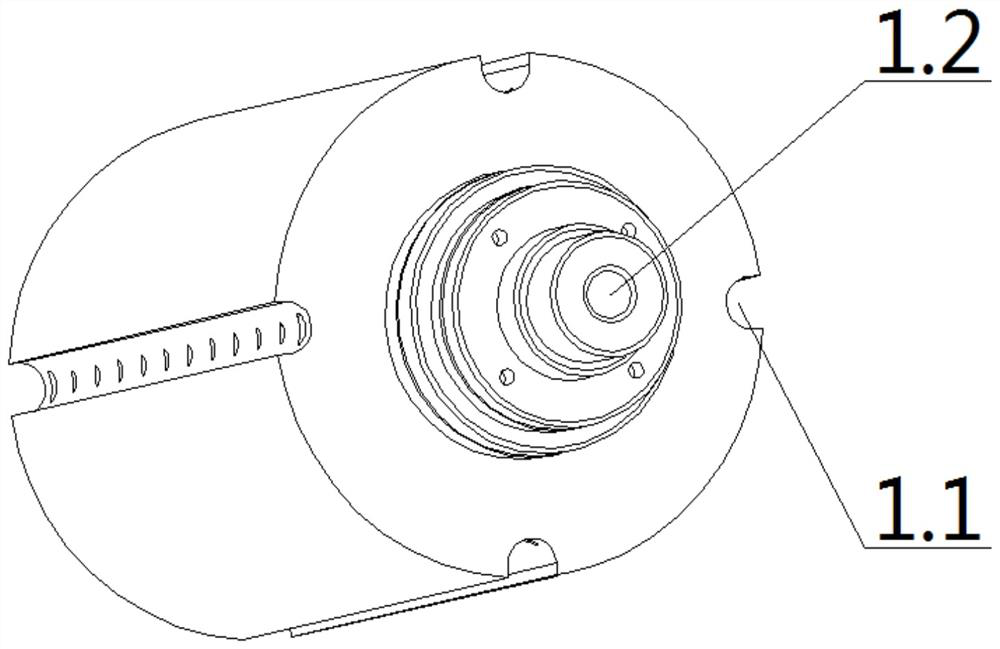
[0020] A composite high-precision plate-shaped roller, including a mandrel 1, a sleeve 2, and a sensor 3; the mandrel 1 is a stepped shaft, and a central threading hole 1.2 is provided in the middle, and the outer diameter of the section with the largest diameter in the middle is evenly spaced around the axis. There are four mandrel U-shaped grooves 1.1, and ten sensor installation holes 1.1.1 are arranged on the middle bottom of the mandrel U-shaped groove 1.1, and sensor threading holes 1.1.2 are arranged at the bottom of both ends of the mandrel U-shaped groove 1.1, and the sensor is threaded The hole 1.1.2 is connected with the central threading hole 1.2; the sleeve 2 is in the shape of a circular tube, and the inner surface of the sleeve 2 is provided...


PUM


Abstract

The invention discloses a composite high-precision plate roller which comprises a mandrel, a sleeve and a sensor. The mandrel is a stepped shaft, a plurality of mandrel U-shaped grooves are evenly distributed in the outer diameter of the section, with the largest diameter, of the middle of the mandrel around the axis, the mandrel U-shaped grooves are machined through a forming milling cutter, andthe technical problems of straightness of deep hole machining and axis parallelism between holes in the prior art are solved. The sleeve is in a circular tube shape, the diameter of an inner hole of the sleeve is large, grinding machining or boring machining is adopted for final machining, and the technical problems of cylindricity and hole surface quality of previous deep hole machining are solved. Therefore, the detection sensitivity and accuracy of the composite high-precision plate type roller on the flatness of a metal plate and a strip are greatly improved, the current production detection requirements of the metal plate and the strip are met, and the technical problems in the technical field of production detection of the metal plate and the strip are successfully solved.

Description

technical field [0001] The invention relates to the technical field of detecting the flatness of the surface of steel, copper, aluminum and other metal plates and strips, in particular to a composite high-precision plate shape roller. Background technique [0002] In the past, the plate-shaped roller used to detect the flatness of the surface of steel, copper, aluminum and other metal plates and strips has an integral structure. The axes of the rollers are evenly distributed, and run through the entire roller body along the axis of the plate-shaped roller. The circular hole for installing the sensor belongs to deep hole processing, which is difficult to process and poor in processing quality. The straightness of the hole and the parallelism of the axes between the holes , hollow cylindricity, and surface quality of the hole cannot be guaranteed; while the processing quality of the circular hole where the sensor is installed has a decisive impact on the detection sensitivity ...

Claims


Application Information

Patent Timeline
Patent Type & Authority Applications(China)
IPC IPC(8): G01B5/28G01B5/252
CPCG01B5/28G01B5/252
Inventor 郭会侠程建国马超门转平
Owner CHINA NON-FERROUS METALS PROCESSING TECH CO LTD
Learn More