Display substrate

A technology of display substrate and display area, which is applied in the manufacture of electrical components, electric solid-state devices, and semiconductor/solid-state devices, etc., can solve the problems of damage to the display screen, large frame width, and unfavorable screen-to-screen aesthetics of mobile terminals, etc. The effect of ensuring the packaging effect, increasing the screen ratio, and reducing the number of partition walls

Active Publication Date: 2021-04-02
HEFEI VISIONOX TECH CO LTD
View PDF16 Cites 2 Cited by
  • Summary
  • Abstract
  • Description
  • Claims
  • Application Information

AI Technical Summary

Problems solved by technology

In order to increase the screen occupancy rate, in the prior art, a laser is used to make a hole of a relatively large size on the display screen, which is suitable for the camera of a mobile phone, but water vapor easily invades the inside of the display screen through the hole and damages the display screen. A partition area is set around the opening to block water vapor, but the border width of the existing partition area is relatively large, which is not conducive to improving the screen ratio and aesthetics of the mobile terminal

Method used


Image

  • Display substrate
  • Display substrate
  • Display substrate

Examples


Embodiment Construction

[0026] Features and exemplary embodiments of various aspects of the invention will be described in detail below. In the following detailed description, numerous specific details are set forth in order to provide a thorough understanding of the present invention. It will be apparent, however, to one skilled in the art that the present invention may be practiced without some of these specific details. The following description of the embodiments is only to provide a better understanding of the present invention by showing examples of the present invention.

[0027] It should be noted that in this article, relational terms such as first and second are only used to distinguish one entity or operation from another entity or operation, and do not necessarily require or imply that there is a relationship between these entities or operations. any such actual relationship or order exists between them. Furthermore, the term "comprises", "comprises" or any other variation thereof is in...


PUM


Abstract

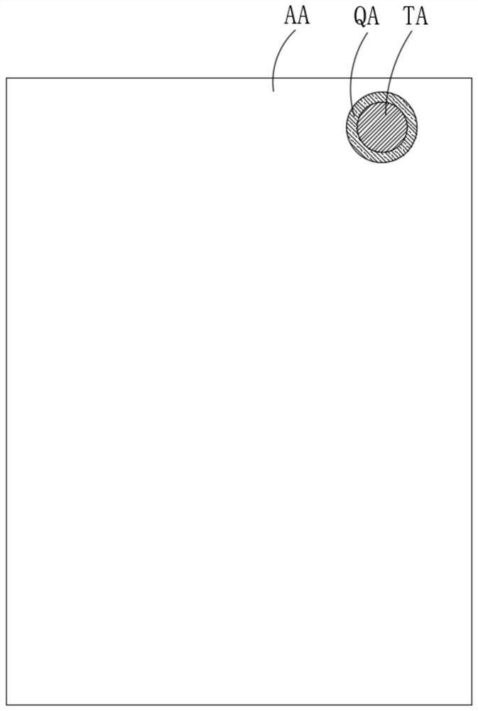
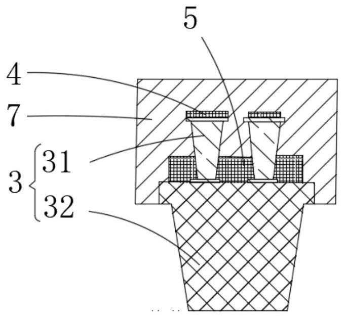
The invention discloses a display substrate which is provided with a hole area, a partition area and a display area, the partition area is at least partially arranged around the hole area, the partition area is located between the hole area and the display area, and the display substrate comprises a substrate body, a display function part arranged on one side of the substrate in the display area and comprising a first luminescent material layer, and a partition assembly arranged in the partition area; the partition assembly and the display function part are arranged in a spaced mode, the partition assembly comprises at least one partition wall, and each partition wall comprises a first partition part and a second partition part which are stacked in the film layer stacking direction of thedisplay substrate; the sides, away from the substrate body, of the second partition parts are covered with second light-emitting material layers, and the portions, exposed by the intervals between thesecond partition parts, of the first partition parts are covered with third light-emitting material layers. By arranging the first partition parts and the second partition parts which are arranged inthe stacked mode, the number of partition walls needing to be arranged in the partition area is reduced while the packaging effect is guaranteed, and the screen-to-body ratio of the display substrateis increased.

Description

technical field [0001] The invention belongs to the technical field of electronic products, and in particular relates to a display substrate. Background technique [0002] With the advancement of science and technology, digital display devices such as smartphones and tablet computers are widely used, and display screens are indispensable human communication interfaces in these display devices. Such as organic light emitting diode (Organic Light Emitting Diode, OLED) display panel has the advantages of self-illumination, energy saving and consumption reduction, bendable, good flexibility, etc., and the display device for realizing display does not require a backlight source, and has fast response and The feature of good display effect has attracted the attention of users and is widely used in terminal products such as smart phones and tablet computers. [0003] With the rapid development of electronic devices, users have higher and higher requirements for screen-to-body rati...

Claims


Application Information

Patent Timeline
Patent Type & Authority Applications(China)
IPC IPC(8): H01L51/52H01L27/32
CPCH10K59/12H10K50/84H10K50/846
Inventor 王守坤秦韶阳赵成雨孙增标
Owner HEFEI VISIONOX TECH CO LTD
Why Eureka
Try Eureka