
Fault monitoring method of explosion-proof motor

An explosion-proof motor and fault monitoring technology, applied in the direction of electrical components, electromechanical devices, electric components, etc., can solve problems such as unfavorable promotion and application, damage to the motor, and impact on service life, and achieve easy promotion and application, strong anti-drying performance, and structural simplified effect

Active Publication Date: 2021-04-02
江苏星宇电机有限公司
View PDF5 Cites 1 Cited by
  • Summary
  • Abstract
  • Description
  • Claims
  • Application Information

AI Technical Summary

Problems solved by technology

The reason for the explosion of the explosion-proof motor is related to the mechanical failure during operation. These mechanical failures are mainly the severe wear of the bearing or the bending of the main shaft. These failures will cause the rotor and the stator to rub against each other to generate sparks or the temperature in the casing will be too high to cause an explosion. After an explosion, the motor will be damaged and its service life will be affected. Therefore, it is necessary to monitor the fault of the explosion-proof motor to avoid the explosion. The existing monitoring method is to detect the vibration amplitude and frequency of the main shaft, and then analyze it to determine whether there is a fault. , this monitoring method is relatively complicated, and the required detection device is expensive, which is not conducive to popularization and application

Method used


Image

  • Fault monitoring method of explosion-proof motor
  • Fault monitoring method of explosion-proof motor
  • Fault monitoring method of explosion-proof motor

Examples


Embodiment Construction

[0011] The specific embodiment of the present invention will now be described in conjunction with the accompanying drawings.

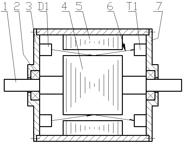
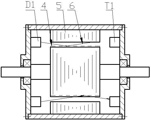
[0012] A fault monitoring method for an explosion-proof motor, such as figure 1 As shown, the light-emitting diode D1 of the photoelectric sensor GE is installed on the front cover 3 of the explosion-proof motor, the phototransistor T1 of the photoelectric sensor GE is installed on the rear end cover 7 of the explosion-proof motor, and the light beam emitted by the light-emitting diode D1 passes through the gap between the stator and the rotor. The air gap between reaches the phototransistor T1.

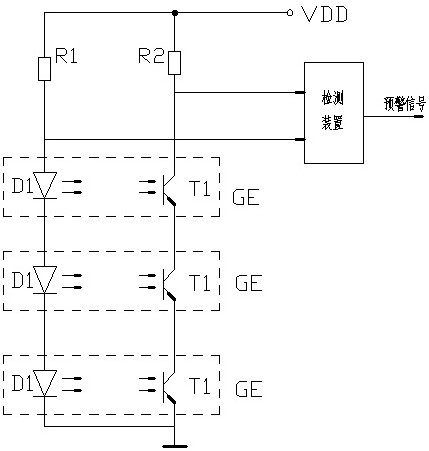
[0013] A detection device judges the state signal of the phototransistor T1 and the tube voltage drop signal of the light-emitting diode D1. The detection circuit is as follows: image 3 As shown, the collector of the phototransistor T1 is connected to the DC power supply VDD through the resistor R2, the emitter of the phototransistor T1 is grounded, the ano...


PUM


Abstract

The invention discloses a fault monitoring method of an explosion-proof motor, which is characterized in that a light-emitting diode of a photoelectric sensor is installed on a front end cover of theexplosion-proof motor, a phototriode of the photoelectric sensor is installed on a rear end cover of the explosion-proof motor, and a light beam emitted by the light-emitting diode penetrates throughan air gap between a stator and a rotor to reach the phototriode; a detection device is adopted to judge the state signal of the phototriode and the tube voltage drop signal of the light emitting diode, and when the phototriode is in a cut-off state, the detection device outputs a rotor eccentricity early warning signal; and when the tube voltage of the light emitting diode is reduced to a specified value, the detection device outputs a high-temperature early warning signal. The method is advantaged in that the eccentric condition of the rotor is detected through light beams, the anti-interference performance is high, and when the anti-explosion motor has mechanical faults or the temperature is too high, an early warning signal can be reliably output; the fault judgment method is simple and convenient, the structure of the detection device can be greatly simplified, and popularization and application are facilitated.

Description

technical field [0001] The invention relates to a fault monitoring method for an explosion-proof motor. Background technique [0002] The explosion-proof motor has an explosion-proof function, which can prevent the explosion flame from escaping out of the casing and contacting with flammable and explosive media. The reason for the explosion of the explosion-proof motor is related to the mechanical failure during operation. These mechanical failures are mainly the severe wear of the bearing or the bending of the main shaft. These failures will cause the rotor and the stator to rub against each other to generate sparks or the temperature in the casing will be too high to cause an explosion. After an explosion, the motor will be damaged and its service life will be affected. Therefore, it is necessary to monitor the fault of the explosion-proof motor to avoid the explosion. The existing monitoring method is to detect the vibration amplitude and frequency of the main shaft, and ...

Claims


Application Information

Patent Timeline
IPC IPC(8): H02K11/22H02K11/25
CPCH02K11/22H02K11/25
Inventor 钱华蒋国俊陈春
Owner 江苏星宇电机有限公司
Learn More