
Control circuit system of electronic bird dispeller

A technology for controlling circuits and bird repellents, applied in electronic switches, electrical components, animal repellents, etc., can solve problems such as short lifespan, high energy consumption of sound bird repellents, and bird repellent failures.

Inactive Publication Date: 2014-09-10
SHUANGLIU COUNTY POWER SUPPLY BRANCH STATE GRID SICHUAN ELECTRIC POWER
View PDF3 Cites 8 Cited by
  • Summary
  • Abstract
  • Description
  • Claims
  • Application Information

AI Technical Summary

Problems solved by technology

But these two kinds of bird repellents have their own shortcomings, such as wind bird repellent, which is highly dependent on the natural environment. It needs the help of natural wind to realize the rotation of the wind wheel and realize the bird repelling. The bird repellent is basically ineffective; the sound bird repellent has the problems of high energy consumption and short life, which makes the bird repellent easy to fail

Method used


Image

  • Control circuit system of electronic bird dispeller

Examples


Embodiment 1

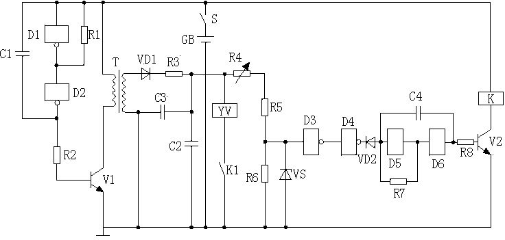
[0025] like figure 1 As shown, the electronic bird repellent control circuit system described in this embodiment includes a multivibrator circuit, a boost circuit, a voltage regulator circuit, a low-frequency oscillation circuit, an electromagnet control circuit and a power supply GB;

[0026] The multivibrator circuit of this embodiment includes a NOT gate circuit D1, a NOT gate circuit D2, a capacitor C1, and a resistor R1. The input terminal of the NOT gate circuit D1 is connected to the positive pole of the power supply GB, and the output terminal of the NOT gate circuit D1 is connected to the NOT gate circuit D1. The input end of the gate circuit D2 is connected; one end of the capacitor C1 is connected to the positive pole of the power supply GB, and the other end is connected to the output end of the NOT gate circuit D2; one end of the resistor R1 is connected to the positive pole of the power supply GB, and the other end is connected to the positive pole of the NOT gate...


PUM


Abstract

The invention discloses a control circuit system of an electronic bird dispeller. The control circuit system comprises a multi-resonant oscillating circuit, a boosting circuit, a voltage stabilizing circuit, a low-frequency oscillating circuit, an electromagnet control circuit and a power supply GB, wherein the multi-resonant oscillating circuit comprises a NOT gate circuit D1, a NOT gate circuit D2, a capacitor C1 and a resistor R1; the boosting circuit comprises a transistor V1, a boosting transformer T, a rectifier diode VD1, a resistor R3, a polar capacitor C2 and a capacitor C3; the low-frequency oscillating circuit comprises a NOT gate circuit D3, a NOT gate circuit D4, a NOT gate circuit D5, a NOT gate circuit D6, a resistor R7, a capacitor C4 and a diode VD2; the electromagnet control circuit comprises a transistor V2, a relay K and an electromagnet YV. With use of such a structure mentioned above, the control circuit system of the electronic bird dispeller disclosed by the invention can effectively reduce energy consumption of the bird dispeller, especially a sound bird dispeller, prolong a service life of the bird dispeller, and simultaneously enable a working status of the bird dispeller to be steadier.

Description

technical field [0001] The invention relates to the field of bird repellers, in particular to a control circuit system of an electronic bird repeller. Background technique [0002] For the power industry, various bird damage is one of the important reasons for short circuit and ground fault. Therefore, in order to ensure the safety of power grid transmission lines and avoid power accidents caused by bird activities, various bird repellents should be And born, such as sound bird repellent, optical bird repellent, wind bird repellent, ultrasonic bird repellent. At present, sound bird repellent and wind bird repellent are widely used. The working principle of sound bird repellent is to drive away birds by continuously making sounds that scare birds; and wind bird repellent It uses wind as the power source, adopts unique bearings, and installs lenses on the wind wheel, so that when the wind wheel does repeated movements, it uses the principle of optical reflection to form an as...

Claims


Application Information

Patent Timeline
IPC IPC(8): H03K17/94A01M29/16
Inventor 李燕史华勃汤凡
Owner SHUANGLIU COUNTY POWER SUPPLY BRANCH STATE GRID SICHUAN ELECTRIC POWER
Learn More