
Turnover solar power generation equipment with variable illumination intensity

A technology of light intensity and power generation equipment, which is applied in the field of flipping solar power generation equipment, can solve the problems that solar power generation is easily affected by light, power generation is reduced, and the use environment is limited, so as to achieve high-efficiency power generation, reduce limiting factors, and increase universality Effect

Active Publication Date: 2021-04-02
HEBEI ZHONGRUN COMM EQUIP CO LTD
View PDF6 Cites 0 Cited by
  • Summary
  • Abstract
  • Description
  • Claims
  • Application Information

AI Technical Summary

Problems solved by technology

[0002] With the development of society, people continue to develop and utilize new energy, including the use of solar energy. Solar photovoltaic power generation refers to the power generation method that directly converts light energy into electrical energy without going through a thermal process. It includes photovoltaic power generation, photochemical power generation , photoinduction power generation and photobiological power generation. Photovoltaic power generation is a direct power generation method that uses solar-grade semiconductor electronic devices to effectively absorb solar radiation energy and convert it into electrical energy. However, solar photoelectric power generation is easily affected by light. Once the light is weakened, its The power generation will also be reduced, which makes its use environment limited

Method used


Image

  • Turnover solar power generation equipment with variable illumination intensity
  • Turnover solar power generation equipment with variable illumination intensity
  • Turnover solar power generation equipment with variable illumination intensity

Examples


Embodiment Construction

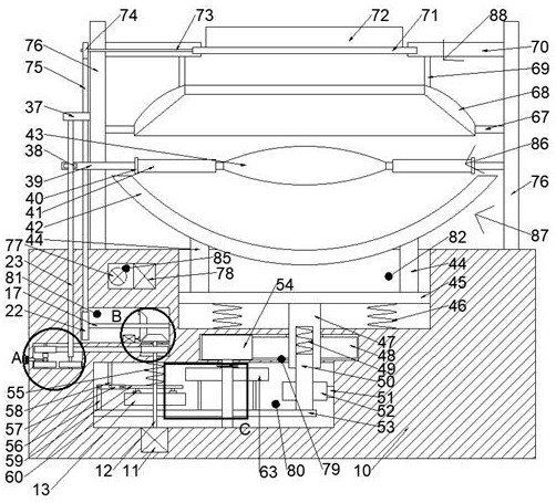
[0018] Combine below Figure 1-4 The present invention is described in detail, wherein, for the convenience of description, the orientations mentioned below are defined as follows: figure 1 The up, down, left, right, front and back directions of the projection relationship itself are the same.

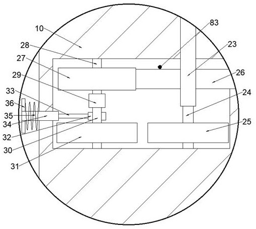
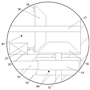
[0019] A flip solar power generation device with variable light intensity of the device of the present invention includes a body 10, a power chamber 80 is arranged in the body 10, a gear chamber 79 is arranged on the upper side of the power chamber 80, and a gear chamber 79 is arranged on the gear chamber 79. The side is provided with a rotating chamber 82, the left side of the body 10 is provided with a lifting chamber 83, the left side of the gear chamber 79 is provided with a control chamber 81, the lower side of the control chamber 81 is provided with a pulley chamber 84, and the control chamber 81 is provided with a detection cavity 85 on the upper side of the body 10. Two suppor...


PUM


Abstract

The invention discloses turnover solar power generation equipment with variable illumination intensity. The equipment comprises a machine body, a power cavity is formed in the machine body, a gear cavity is formed in the upper side of the power cavity, a rotating cavity is formed in the upper side of the gear cavity, a lifting cavity is formed in the left side of the machine body, a control cavityis formed in the left side of the gear cavity, a belt wheel cavity is arranged in the lower side of the control cavity, a detection cavity are formed in the upper side of the control cavity, two supporting columns are fixedly arranged on the upper side face of the machine body, a top plate is fixedly arranged on the upper side of each supporting column, a switching device used for rotating and overturning the illumination face is arranged on the upper side of each supporting column, a light condensation device used for adjusting light condensation is arranged in the middle of each supportingcolumn, and a rotating device used for reflecting illumination is arranged on the upper side of the machine body. The equipment can automatically absorb sunlight for generating power, when the sunlight becomes weak, the sunlight is collected through reflection and focusing, and efficient power generation is achieved, so that the equipment can be used in an environment with small illumination, limiting factors of solar power generation are reduced, and the use universality of the device is improved.

Description

technical field [0001] The invention relates to the related field of solar energy equipment, in particular to a reversible solar power generation equipment with variable light intensity. Background technique [0002] With the development of society, people continue to develop and utilize new energy, including the use of solar energy. Solar photovoltaic power generation refers to the power generation method that directly converts light energy into electrical energy without going through a thermal process. It includes photovoltaic power generation, photochemical power generation , photoinduction power generation and photobiological power generation. Photovoltaic power generation is a direct power generation method that uses solar-grade semiconductor electronic devices to effectively absorb solar radiation energy and convert it into electrical energy. However, solar photoelectric power generation is easily affected by light. Once the light is weakened, its The amount of power g...

Claims


Application Information

Patent Timeline
Patent Type & Authority Applications(China)
IPC IPC(8): H02S40/22H02S40/30
CPCH02S40/22H02S40/30Y02E10/52
Inventor 余健建
Owner HEBEI ZHONGRUN COMM EQUIP CO LTD
Learn More