[0039] The following will clearly and completely describe the technical solutions in the embodiments of the present invention with reference to the accompanying drawings in the embodiments of the present invention. Obviously, the described embodiments are only some, not all, embodiments of the present invention. Based on the embodiments of the present invention, all other embodiments obtained by persons of ordinary skill in the art without creative efforts fall within the protection scope of the present invention.
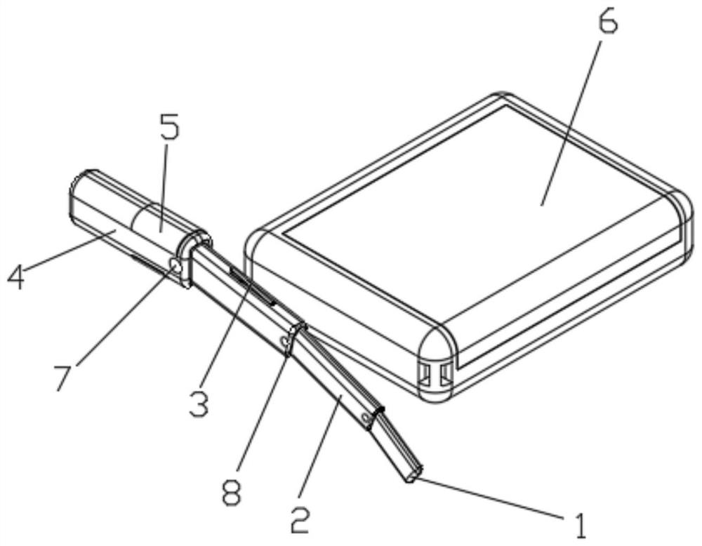
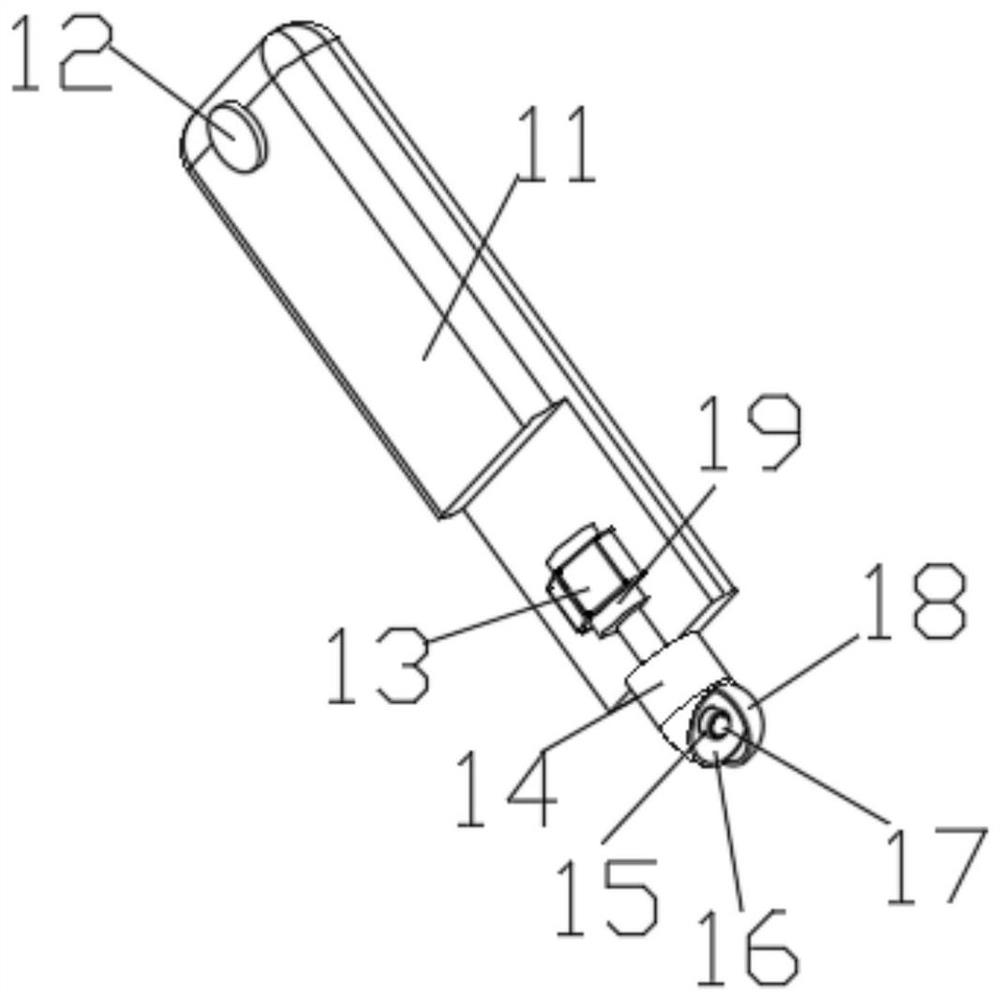
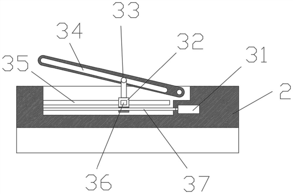
[0040] see Figure 1-9 , the present invention provides a technical solution: a portable wireless video laryngoscope, including a camera base 1, a telescopic rod 2, a throat fixing clip 3, a handle 4, an oral cavity top frame 5, a placement box 6, a fixing button 7 and The connecting frame 8, the end of the telescopic rod 2 is slidingly connected with the front end of the handle 4 through the connecting frame 8, the front end of the telescopic rod 2 is slidingly connected with the camera seat 1 through the connecting frame 8, the telescopic rod 2 is multi-section, and each section of the telescopic rod 2 passes through The connecting frame 8 is slidingly connected, the telescopic rod 2 and the handle 4 side walls are all provided with a fixed button 7, the fixed button 7 cooperates with the connecting frame 8, the oral cavity top frame 5 is arranged on the handle 4 outer side wall, and the telescopic rod 2 outside The wall is provided with a throat clamp 3, a camera is provided on the camera base 1, the camera base 1, the telescopic rod 2, the throat clamp 3, the handle 4, the oral cavity top frame 5, the fixing button 7 and the connecting frame 8 are all placed In the placement box 6, the handle 4 is provided with a wireless charging receiver and a handle battery, and the camera seat 1 is provided with a signal transceiver device, and the camera signal transceiver device is electrically connected to the handle battery.
[0041] The placement box 6 includes a placement box body 61, the inside of the placement box body 61 is provided with a battery, a control circuit and a signal transceiver, the battery is electrically connected to the control circuit and the signal transceiver, and the display screen 63 and the control button 67 are electrically connected to the control circuit. Connection, the bottom of the handle placement groove 64 is embedded with a wireless charging device, the wireless charging device is electrically connected with the control circuit, the wireless charging device is matched with the wireless charging receiver, and the signal transceiver is matched with the camera signal transceiver. The wireless charging circuit adopts Xinketai xkt408a.
[0042] like figure 2 As shown, the camera seat 1 includes a base 11, a camera rotating shaft 12, a motor fixing frame 13, a camera mounting base 14, an annular fill light 15, a condenser cover 16, a camera 17, a protective cover 18 and a motor 19, and the base 11 is a strip Shape, base 11 end left and right side walls are fixed with camera rotating shaft 12, base 11 is connected with connecting frame 8 through the rotation of camera rotating shaft 12, motor 19 is fixed on the inside of front end of base 11 by motor fixing frame 13, motor 19 is connected with camera mount by output shaft 14 ends are fixedly connected, and the front end of the camera mount 14 is provided with a spotlight cover 16, the camera 17 is fixedly installed in the center of the spotlight cover 16, and the outside of the camera 17 is surrounded by a ring fill light 15, and the protective cover 18 is located at the camera mount 14 The front end, and the protective cover 18 covers the outside of the ring fill light 15 and the camera 17, and the ring fill light 15 and the camera 17 are electrically connected with the camera signal transceiver device.
[0043] like image 3 As shown, the throat clamp 3 includes a clamp drive motor 31, a support slider 32, a clamping arm 33, a clamping wall chute 34, a slider limit chute 35, a limit block 36 and a threaded screw 37, The fixing clip driving motor 31 is fixedly embedded in the inner side of the telescopic rod 2, the threaded screw rod 37 is rotated and fixed in the inner side of the telescopic rod 2, and one end of the threaded screw rod 37 is fixedly connected with the output shaft of the fixing clip driving motor 31, and the clamping arm 33 is embedded in the On the telescopic rod 2, and one end of the clamping arm 33 rotates and cooperates with the telescopic rod 2 through the rotating shaft, the clamping wall 33 is provided with a clamping wall chute 34, and the position of the clamping arm 33 is provided with a through groove on the telescopic rod 2, The wall of the through groove is provided with a slider limit chute 35, the supporting slider 32 is located in the through groove of the telescopic rod 2, and the supporting slider 32 is slidably matched with the telescopic rod 2, and the left and right side walls of the supporting slider 32 are all fixed and limited. The position block 36, the limit block 36 is slidably arranged in the slider limit chute 35, the upper end of the support slider 32 is arranged in the clamping wall chute 34, and the upper end of the support slider 32 and the clamping wall chute 34 rotate and slide In cooperation, the threaded screw rod 37 penetrates the lower side of the support slider 32 , and the threaded screw rod 37 is threadedly matched with the support slider 32 .
[0044] like Figure 4 As shown, the oral cavity roof frame 5 includes an upper jaw roof frame and a lower jaw roof frame. The structure of the upper jaw roof frame and the lower jaw roof frame is exactly the same. The top frame includes the upper jaw top frame drive motor 51, the upper jaw top plate 52, the top plate fixed block 53, the top plate support rocker 54, the top plate slider 55 and the top plate screw rod 56, the upper jaw top frame drive motor 51 is embedded in the inside of the handle 4, the top plate The screw mandrel 56 is rotatably fixed on the handle 4, and one end of the top plate screw mandrel 56 is rotationally connected with the handle 4, and the other end is fixedly connected with the output shaft of the upper jaw top frame driving motor 51. The upper jaw top plate 52 is arranged on the upper side of the handle 4, and the upper jaw The lower end surface of the top plate 52 is fixed with a top plate fixing block 53, and there are two top plate fixing blocks 53. The connection direction is arranged. The top plate screw rod 56 is covered with a top plate slider 55. There are two top plate sliders 55. The two top plate sliders 55 are threaded with the top plate screw rod 56, and the inside of the two top plate sliders 55 The thread direction is opposite, and the top plate slider 55 and the top plate fixed block 53 are fixedly connected by the top plate support rocker arm 54. 55 are connected in rotation, and the upper end surface of the upper jaw top plate 52 is provided with a soft rubber pad.
[0045] like Figure 5 As shown, the placement box 6 also includes a box cover 62, a display screen 63, a handle placement groove 64, a throat placement groove 65, a spring buckle 66, a control button 67 and a spring block 68, and the placement box body 61 is rectangular, and the box Cover 62 is located on the upper side of the box body 61, and the box cover 62 is rotatably matched with the box body 61. The inner surface of the box cover 62 is fixed with a display screen 63, and the upper end surface of the box body 61 is provided with a handle placement groove 64, The throat placement groove 65 and the control button 67, the spring buckle 66 is slidingly embedded in the edge of the upper end surface of the box body 61, the spring buckle 66 cooperates with the inner side wall of the lower end surface of the inner side wall of the box cover 62, and the handle is placed on the inner side wall of the groove 64 The spring blocks 68 are arranged symmetrically.
[0046] like Image 6 As shown, the spring block 68 includes a block spring 681 and a movable block 682, the movable block 682 is embedded on the inner wall of the handle placement groove 64, and the movable block 682 is slidingly fitted with the handle placement groove 64, and the movable block The block 682 is connected with the handle placement groove 64 through the block spring 681 .
[0047] like Figure 7 As shown, the spring buckle 66 includes a buckle spring 661, a buckle 662 and a button 663. The button 663 is fixed on the lower side of the front end of the buckle 662. The buckle 662 is slidably arranged on the edge of the upper end surface of the storage box 6, and the button 663 is placed through it. The box 6 extends outside the side wall of the box 6, and the buckle spring 661 is embedded in the box 6, and one end of the buckle spring 661 is fixedly connected with the box 6, and the other end is fixedly connected with the rear end of the buckle 662.
[0048] like Figure 8As shown, the fixed button 7 includes a button body 71, a limit ring 72, a limit extrusion spring 73 and a locking limit hole 74. The button body 71 is a cylinder, and the limit ring 72 is fixedly sleeved on the outer wall of the button body 71. The button body 71 is embedded in the handle 4, and the button body 71 is slidingly fitted with the handle 4. One end of the button body 71 penetrates the side wall of the handle 4, and the other end is located inside the handle 4, and the corresponding end of the handle 4 The side wall is provided with a lock limit hole 74, the lock limit hole 74 and the button body 71 are combined to run through the handle 4, the limit squeeze spring 73 is sleeved on the button body 71, and one end of the limit squeeze spring 73 is connected to the lock limit The hole 74 is fixedly connected, and the other end is fixedly connected with the limit ring 72. The handle 4 and the telescopic rod 2 are all provided with a fixed button 7, and all the fixed buttons 7 have the same structure.
[0049] like Figure 9 As shown, the connecting frame 8 includes a connecting frame block 81, a connecting frame spring 82, a connecting frame body 83, a rotating shaft groove 84, an extruding screw 85 and a limit snap ring 86, and the connecting frame body 83 is a hollow rectangular block without a top. A limit snap ring 86 is fixed on the outer wall of the bottom end of the frame body 83, and the connecting frame body 83 is slidably fixed on the inside of the handle 4 and the telescopic rod 2 by the limit snap ring 86. The side wall of the connecting frame body 83 is provided with a shaft groove 84, and the other The side wall is slidingly embedded with a connecting frame block 81, which is connected to the connecting frame body 83 through the connecting frame spring 82, and the inner thread of the shaft groove 84 is equipped with an extrusion screw 85, which penetrates the handle 4 and the telescopic rod 2 extend outside, the connecting frame block 81 is matched with the locking limit hole 74, and the rotating shaft groove 84 is matched with the camera rotating shaft 12.
[0050] The working steps of a portable wireless video laryngoscope are as follows:
[0051] 1) When in use, press the button 663 to separate the buckle 662 from the box cover 62, and pull the box cover 62 upward to make the box cover 62 rotate to the maximum position along the connection between the box cover 62 and the storage box body 61;
[0052] 2) Press the movable block 682, and take out the handle 4 from the handle placement groove 64;
[0053] 3) Pull the camera seat 1 to pull out the camera seat 1 and the telescopic rod 2 from the handle 4 in turn, so that the connecting frame block 81 snaps into the locking limit hole 74;
[0054] 4) Turn the telescopic rod 2 and the camera seat 1 to form a shape suitable for the throat structure of the patient, and turn the extruding screw 85 so that the extruding screw 85 clamps the camera rotating shaft 12;
[0055] 5) Insert the throat pipe from one end of the camera base 1 to the direction of the handle 4, and start the clamp drive motor 31 through the control button 67, so that the support slider 32 moves along the threaded screw rod 37, and then the clamping wall chute 34 Rotate to tighten the throat;
[0056] 6) Insert one end of the camera seat 1 into the throat of the patient, start the upper jaw drive motor 51 through the control button 67, and make the two top plate sliders 55 move in opposite directions, and then make the upper jaw top plate 52 away from the handle 4, and then support the patient's mouth live;
[0057] 7) Start the motor 19 through the control button 67 to rotate the camera mount 14, and simultaneously start the ring fill light 15 and the camera 17, and the camera 17 takes real-time pictures of the throat and transmits the data to the display screen 63;
[0058] 8) Reversely activate the fixing clip drive motor 31 through the control button 67, so that the support slider 32 moves in the reverse direction along the threaded screw rod 37, and then the clamping wall chute 34 is rotated, and the throat is released;
[0059] 9) At this time, reversely start the drive motor 51 of the upper jaw top frame to keep the two top plate sliders 55 away, and then make the upper jaw top plate 52 close to the handle 4, separate the patient's upper jaw top plate 52 from the patient's oral cavity, and pull out the camera seat 1;
[0060] 10) After use, clean and disinfect the camera base 1, telescopic rod 2 and handle 4;
[0061] 11) Turn the extruding screw 85 reversely to separate the extruding screw 85 from the camera shaft 12, and rotate the camera seat 1 and the telescopic rod 2 to the level of the handle 4;
[0062] 12) Press the button body 71 to disengage the connecting frame block 81 from the locking limit hole 74, push the camera seat 1 to insert the camera seat 1 and the telescopic rod 2 into the handle 4;
[0063] 13) Put the handle 4 into the handle placement groove 64, lock it by the spring block 68, close the device, and buckle the box cover 62 on the box body 61.
[0064] The above content is only an example and description of the structure of the present invention. Those skilled in the art make various modifications or supplements to the described specific embodiments or replace them in similar ways, as long as they do not deviate from the structure of the invention or Anything beyond the scope defined in the claims shall belong to the protection scope of the present invention.
[0065] The preferred embodiments of the invention disclosed above are only to help illustrate the invention. The preferred embodiments are not exhaustive in all detail, nor are the inventions limited to specific embodiments described. Obviously, many modifications and variations can be made based on the contents of this specification. This description selects and specifically describes these embodiments in order to better explain the principles and practical applications of the present invention, so that those skilled in the art can well understand and utilize the present invention. The invention is to be limited only by the claims, along with their full scope and equivalents.