An all-round painting machine for ring parts of new energy vehicles

A new energy vehicle, all-round technology, applied in the direction of injection devices, etc., can solve the problems of inaccurate placement of accessories, troublesome rotation of accessories, damaged accessories, etc., to achieve the effect of convenient rotation of accessories, quality assurance, and accurate placement

Active Publication Date: 2021-08-24
JIANGXI COLLEGE OF APPLIED TECH
View PDF0 Cites 0 Cited by
  • Summary
  • Abstract
  • Description
  • Claims
  • Application Information

AI Technical Summary

Problems solved by technology

[0005] In order to overcome the shortcomings of the existing technology that may damage the accessories, hold the accessories, consume physical strength, the location of the accessories may be inaccurate, and the shortcomings of rotating the accessories are troublesome. The technical problem to be solved: provide a simple way to paint the ring accessories to avoid damage to the accessories , to facilitate the placement of accessories, to ensure that the accessories can be fixed smoothly, and it is more labor-saving to realize the all-round painting of ring accessories. The all-round painting machine for ring accessories of new energy vehicles

Method used


Image

  • An all-round painting machine for ring parts of new energy vehicles
  • An all-round painting machine for ring parts of new energy vehicles
  • An all-round painting machine for ring parts of new energy vehicles

Examples


Embodiment 1

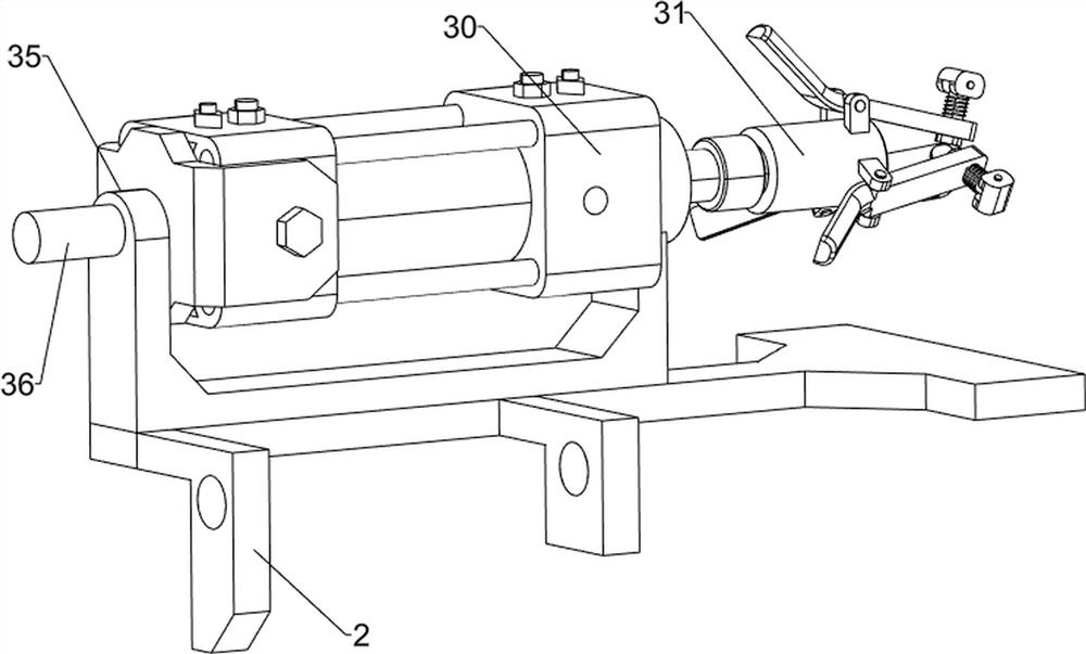
[0031] An all-round painting machine for ring parts of new energy vehicles, such as figure 1 , figure 2 , image 3 , Figure 4 and Figure 5 As shown, it includes a support 1, a support plate 2, a clamping mechanism 3 and a spraying mechanism 4. The upper part of the support 1 is connected with a support plate 2, the left side of the upper part of the support plate 2 is provided with a clamping mechanism 3, and the right side of the lower part of the support 1 is provided with There are spraying mechanism 4.

[0032] The clamping mechanism 3 includes a cylinder 30, a guide sleeve 31, a first connecting rod 32, a first spring 33, a top block 34, a mounting seat 35 and a first rotating shaft 36, and the left side of the upper part of the support plate 2 is connected with the mounting seat 35. The left side of the seat 35 top is rotatably connected with a first rotating shaft 36, and the right side of the first rotating shaft 36 is equipped with a cylinder 30. Guide sleeve ...

Embodiment 2

[0036] On the basis of Example 1, such as figure 1 , Figure 6 , Figure 7 , Figure 8 , Figure 9 and Figure 10 As shown, a fixed assembly 5 is also included, and the fixed assembly 5 includes a third support block 50, a roller 51, a limit rod 52, a first runner 53, a second runner 54 and a second spring 55, and the upper part of the support plate 2 The right side is connected with a third support block 50, and the right side of the third support block 50 is rotationally connected with a first runner 53, and the first runner 53 is evenly spaced and connected with three stop rods 52, between the three stop rods 52 There is a second runner 54 slidingly connected between them, the second runner 54 cooperates with the first connecting rod 32, the second runner 54 is connected with the third support block 50 in rotation, the second runner 54 is connected with the first runner Between 53, three second springs 55 are connected evenly at intervals, and the second spring 55 is s...


PUM


Abstract

The invention relates to a painting machine, in particular to an all-round painting machine for ring accessories of new energy vehicles. The technical problem to be solved is to provide a new energy vehicle ring fitting that can easily paint the ring fittings to avoid damage to the fittings, facilitate the placement of the fittings, ensure that the fittings can be fixed smoothly, and realize the all-round painting of the ring fittings with less effort. Painting machine. An all-round painting machine for ring accessories of new energy vehicles, including: a bracket, the upper part of the bracket is connected with a support plate; a clamping mechanism, the upper side of the support plate is provided with a clamping mechanism; Spray mechanism. In the present invention, the first connecting rod moves to the right, cooperates with the second runner, pushes the top block to move inwardly, and fastens the fittings, so as to prevent the first connecting rod from damaging the fittings and ensure the quality of the fittings.

Description

technical field [0001] The invention relates to a painting machine, in particular to an all-round painting machine for ring accessories of new energy vehicles. Background technique [0002] Due to the characteristics of energy saving and environmental protection of new energy, the demand is increasing day by day, and it has been popularized in people's daily life. New energy vehicles are composed of various accessories. Paint treatment is required. [0003] The existing paint technology for ring parts of new energy vehicles is to fix the parts and use the nozzle to spray paint onto the parts to paint them. However, in the process of fixing parts, it is easy to damage the parts, and secondly, hold the parts for a long time. , It is laborious and troublesome, and in the process of fixing the accessories, it may not be able to be fixed successfully at one time due to the inaccurate placement of the accessories. In the end, it is necessary to fully rotate the accessories to pai...

Claims


Application Information

Patent Timeline
Patent Type & Authority Patents(China)
IPC IPC(8): B05B13/02
CPCB05B13/0228B05B13/0285
Inventor 姜云斐吴金华邓方
Owner JIANGXI COLLEGE OF APPLIED TECH
Why Eureka
Try Eureka