Angle-adjustable flanging die system

A flanging mold, adjustable technology, applied in the direction of forming tools, manufacturing tools, metal processing equipment, etc., to achieve the effect of flanging body, wide use, and increase the effect of bonding pressing material area

Active Publication Date: 2021-04-06
ANHUI LINGFENG METALLURGICAL MACHINERY
View PDF6 Cites 0 Cited by
  • Summary
  • Abstract
  • Description
  • Claims
  • Application Information

AI Technical Summary

Problems solved by technology

[0007] Aiming at the deficiencies in the prior art that the flanging mold cannot be flexibly applied to the flanging operation in various environments, the present invention provides an angle-adjustable flanging mold system, which can not only flexibly avoid various obstacles, but also further improve the Flanging effect, wider application range

Method used


Image

  • Angle-adjustable flanging die system
  • Angle-adjustable flanging die system
  • Angle-adjustable flanging die system

Examples


Embodiment 1

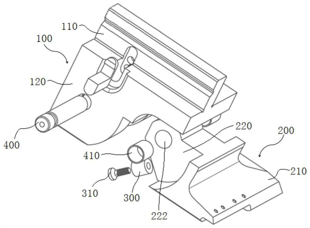
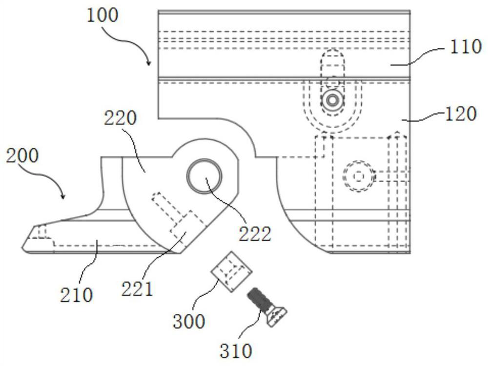
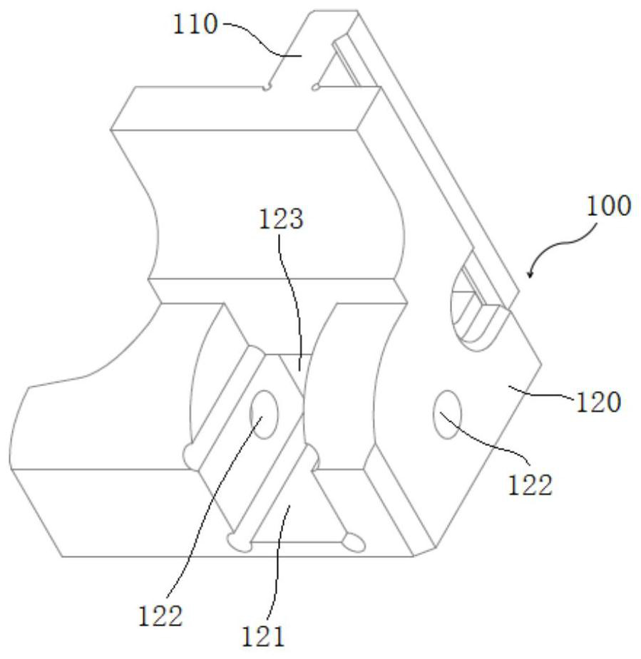
[0037] to combine Figure 1-Figure 4, an angle-adjustable flanging mold system in this embodiment includes a mold handle 100 and a movable part 200 connected in rotation with the mold handle 100. The bottom of the mold handle 100 is provided with an installation cavity 121, and the movable part 200 includes an embedded installation The embedded part 220 in the cavity 121, the embedded part 220 can rotate freely in the installation cavity 121, and the bottom of the embedded part 220 is provided with a binder plate 210, and the binder side of the binder plate 210 is a flat surface, ensuring the The overall plane of the contact with the sharp part, not just the traditional straight line contact, increases the bonding area with the sharp part, improves the flanging effect, and can adapt to the flanging treatment of thicker sharp parts . Specifically, such as figure 2 As shown, in this embodiment, the positions corresponding to the two side walls of the installation cavity 121 i...

Embodiment 2

[0041] An angle-adjustable flanging mold system of this embodiment has the same basic structure as that of Embodiment 1. Further, the limiting hole 221 in this embodiment is a stepped hole, and the inner side of the limiting hole 221 is a The bolt hole matched with the bolt 310, the outer side of the limit hole 221 is a cylindrical hole matched with the limit cylinder 300, that is, a cylindrical hole and a bolt hole are arranged in sequence along the direction close to the inner center of the inner part 220, wherein the diameter of the cylindrical hole greater than the diameter of the bolt hole, the limit cylinder 300 is installed in the cylinder hole, the limit cylinder 300 is provided with a countersunk hole matching the limit bolt 310, the length of the limit bolt 310 exceeds the depth of the cylinder hole, and is smaller than the cylinder hole and the depth of the bolt hole. During installation, the limit bolt 310 is screwed into the countersunk hole inside the limit cylin...

Embodiment 3

[0044] A kind of adjustable angle flanging mold system of this embodiment, the basic structure is consistent with embodiment 1, further, as figure 1 As shown, the mounting hole 122 is provided with an anti-wear sleeve 410 matching with the rotating shaft 400 , and the anti-wear sleeve 410 is sleeved on the outer periphery of the rotating shaft 400 . In this embodiment, the mounting holes 122 on the two side walls of the mounting cavity 121 are also provided with anti-wear sleeves 410 matched with the rotating shaft 400, and the anti-wear sleeves 410 are copper sleeves. The anti-wear sleeve 410 can effectively prevent the wear and tear on the movable part 200 and the mold handle 100 during the rotation process, avoid frequent replacement of the movable part 200 and the mold handle 100 due to the wear of the rotating parts, and reduce the production cost.

[0045] In this embodiment, the mold handle 100 also includes a frame 110 arranged on the top, a connection part 120 is prov...


PUM


Abstract

The invention discloses an angle-adjustable flanging die system, and belongs to the technical field of dies. The angle-adjustable flanging die system comprises a die handle and a movable part rotationally connected with the die handle, wherein a mounting cavity is formed in the bottom of the die handle, the movable part comprises an embedded part embedded into the mounting cavity, the embedded part can freely rotate in the mounting cavity, an adjusting part used for adjusting the distance between the embedded part and the rear side wall is arranged between the embedded part and the rear side wall in the mounting cavity, a material pressing plate is arranged at the bottom of the embedded part, and the material pressing side of the material pressing plate is a flat straight surface. Aiming at the defect that a flanging die in the prior art cannot be flexibly suitable for flanging operation in various environments, the invention provides the angle-adjustable flanging die system, various obstacles can be flexibly avoided, the flanging effect can be further improved, and the application range is wider.

Description

technical field [0001] The invention belongs to the technical field of moulds, and more specifically relates to an angle-adjustable flanging mold system. Background technique [0002] Use the mold to trim the hole edge of the trimmed part and trim the outer edge to trim the straight edge, which is called flanging. Utilize the Flanged Galilee body piece to have a solid body, which is often the case with the Flanged Galilee. In the actual flanging operation, due to the influence of the mold, the shape of the Galilean parts and the on-site operating environment, the traditional linear flanging mold can no longer meet the needs of on-site flanging, so it is urgent to design a flexible and adaptable The flanging mold system of various shapes and operating environments can not only flexibly avoid various obstacles, but also further improve the flanging effect, and the scope of application is wider. [0003] After retrieval, a large number of patents have been published on the re...

Claims


Application Information

Patent Timeline
Patent Type & Authority Applications(China)
IPC IPC(8): B21D37/10
CPCB21D37/10
Inventor 刘道豹姜津刘发仙
Owner ANHUI LINGFENG METALLURGICAL MACHINERY
Why Eureka
Try Eureka