A plastic faucet spool assembly device

A technology for assembling devices and faucets, which is applied to household appliances, other household appliances, household components, etc., can solve the problems of unfavorable production and development of enterprises, long time consumption, large manpower and other problems, so as to reduce the time for replacing the faucet, reduce Manpower consumption and the effect of improving production efficiency

Active Publication Date: 2022-06-07
FUZHOU YINSHENGWANG SANITARY WARE
View PDF16 Cites 0 Cited by
  • Summary
  • Abstract
  • Description
  • Claims
  • Application Information

AI Technical Summary

Problems solved by technology

[0005] In order to overcome the shortcomings that a large amount of manpower is required to manually assemble the faucet valve core, and the manual assembly takes a long time, which is not conducive to the production and development of the enterprise, the purpose of the present invention is to provide a plastic faucet that can be assembled automatically Spool assembly device

Method used


Image

  • A plastic faucet spool assembly device
  • A plastic faucet spool assembly device
  • A plastic faucet spool assembly device

Examples


Embodiment 1

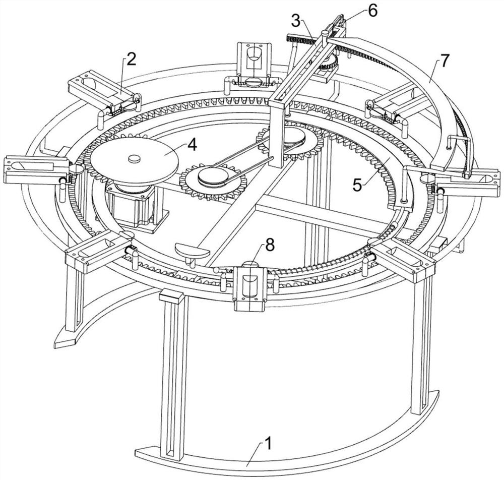
[0030] A plastic faucet spool assembly device, such as Figures 1 through 4 Shown, comprising a bracket 1, a rotating placement assembly 2 and a tightening assembly 3, the upper side of the bracket 1 is provided with a rotating placement assembly 2, the upper side of the bracket 1 is connected to the tightening assembly 3.

[0031] When the faucet needs to be assembled, the faucet and the spool are placed on the rotating placement assembly 2, and then the controlled tightening assembly 3 will be tightened with the spool, and after tightening, the rotation placement assembly 2 can be controlled, which in turn can make the control tightening assembly 3 to assemble the spool of other unassembled faucets, when all the faucets are assembled, the rotation placement assembly 2 and the tightening assembly 3 can no longer be controlled.

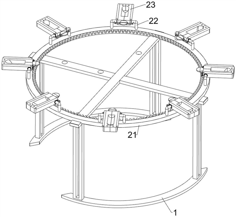
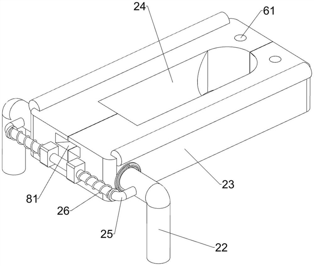
[0032] Rotating placement assembly 2 includes a ring plate 21, a recessed rod 22, a placing plate 23, a concave guide rod 25 and a first spring 26, the up...

Embodiment 2

[0037] On the basis of Example 1, e.g., Figure 1 、 Figure 5 、 Figure 6 、 Figure 7 、 Figure 8 and Figure 9 Shown, further comprising a power component 4, the power component 4 comprises a geared motor 41, a sector gear 42 and a ring gear 43, the left side of the bracket 1 is connected to the gear motor 41, the output shaft of the gear motor 41 is connected to a large sector gear 42, the inner side of the ring plate 21 is provided with a ring of gear 43, the ring of gear 43 and the fan gear 42 mesh.

[0038] When the faucet needs to be assembled with the valve spool, the gear motor 41 is started, and the fan gear 42 is rotated, so that the ring gear 43 is rotated, and then the ring plate 21 is rotated, so that the staff does not need to manually control the rotation of the ring plate 21, reducing the manpower consumed.

[0039] Further comprising a tightening fit assembly 5, a tightening fit assembly 5 includes a ring rail 51, a first curved rack 52, a guide sleeve 53, an arc guide ...


PUM


Abstract

The invention relates to an assembly device, in particular to an assembly device for a plastic faucet valve core. The purpose of the present invention is to provide a plastic faucet spool assembly device capable of automatic assembly. A plastic faucet spool assembly device includes: a bracket; a rotating and placing component installed on the bracket; a tightening component installed on the bracket. The invention has a tightening and fixing component and an automatic fixing component, which can fix the position of the placement plate through the cooperation of the slot and the insertion rod when the faucet is tightened, preventing the placement plate from being separated when the faucet is tightened, thereby affecting the function of the faucet. Assembling; the present invention has a blanking assembly, and through the cooperation of the first convex plate and the second convex plate, the device can separate the plates placed on both sides, thereby facilitating the replacement of the faucet by the staff, reducing the time for replacing the faucet, and improving the Productivity.

Description

Technical field [0001] The present invention relates to an assembly device, in particular to a plastic faucet spool assembly device. Background [0002] Faucet is a common name for water valves, used to control the size of the water flow switch, has the effect of saving water, the production of faucets, the need to assemble the valve spool. [0003] General faucet spool assembly is assembled by hand, manual assembly, the need for staff to fix the faucet with one hand, and then the other hand to tighten the faucet spool, manual operation requires a lot of manpower, and manual assembly takes a long time, is not conducive to the production and development of enterprises. [0004] Therefore, a plastic faucet spool assembly device that can be assembled automatically is required. Contents of the Invention [0005] In order to overcome the manual assembly of the faucet spool requires a lot of manpower, and manual assembly takes a long time, is not conducive to the production and develo...

Claims


Application Information

Patent Timeline
Patent Type & Authority Patents(China)
IPC IPC(8): B29C65/56B29C65/78
CPCB29C65/56B29C65/7841B29C66/834B29L2031/7506
Inventor 肖鹿琦程银华
Owner FUZHOU YINSHENGWANG SANITARY WARE
Why Eureka
Try Eureka