Automatic winding machine for industrial detonating cord production
A detonating cord and winder technology, which is applied to the detonating cord and other directions, can solve the problems of physical exertion, low work efficiency, long time consumption, etc., and achieve the effect of reducing the operating burden
- Summary
- Abstract
- Description
- Claims
- Application Information
AI Technical Summary
Problems solved by technology
Method used
Image
Examples
Embodiment 1
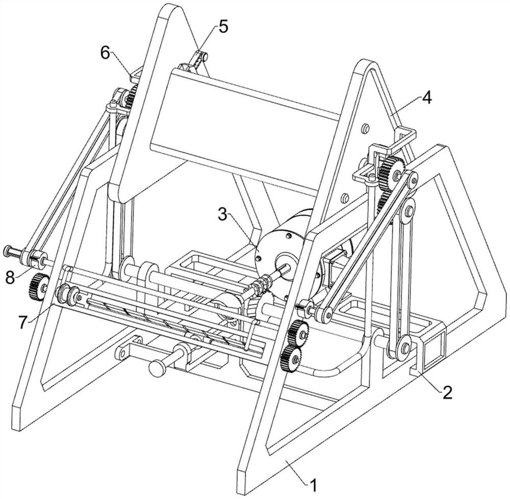
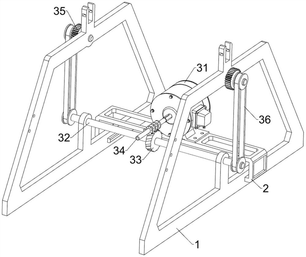
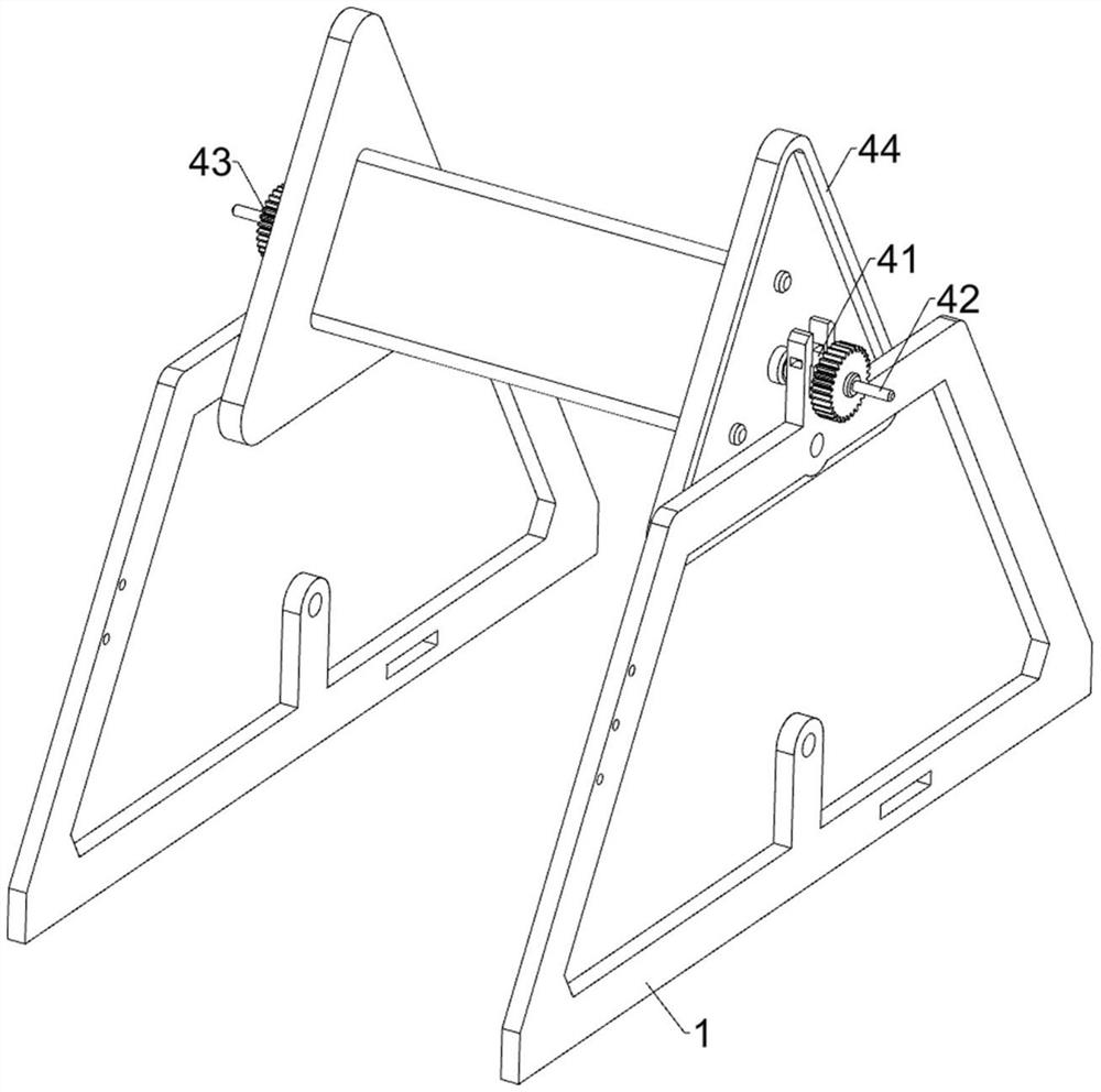
[0027] An automatic winding machine for industrial detonating cord production, such as Figure 1 to Figure 4 As shown, it includes a frame 1, a support frame 2, a drive assembly 3, a winding assembly 4 and a pressing assembly 5, the frame 1 is provided with a support frame 2, and the upper side of the support frame 2 is provided with a drive assembly 3, the machine The frame 1 is provided with a winding assembly 4 , and the winding assembly 4 is provided with a pressing assembly 5 .
[0028] When the industrial detonating cord needs to be rewound, the industrial detonating cord is placed on the winding assembly 4, then the pressing assembly 5 is controlled to fix the industrial detonating cord on the winding assembly 4, and then the driving assembly 3 is started, The driving component 3 will drive the winding component 4 to operate, and then make the winding component 4 wind up the industrial detonating cord, and then close the driving component 3 after the winding is complete...
Embodiment 2
[0036] On the basis of Example 1, such as figure 1 , Figure 5 , Figure 6 and Figure 7 As shown, it also includes a fixed assembly 6, the fixed assembly 6 includes a cam 61, a slide bar 62, a connecting rod 64 and a limit plate 65, the front side of the worm 34 is welded with a cam 61, and the frame 1 is slidably connected with a slide Bar 62, slide bar 62 cooperates with cam 61, and slide bar 62 is connected with connecting rod 64, and the upper left and right sides of connecting rod 64 are all connected limit plate 65, and limit plate 65 cooperates with frame 1.
[0037] Starting the reduction motor 31 will cause the worm 34 to rotate, thereby causing the cam 61 to rotate, thereby pushing the slide bar 62 to move forward, thereby causing the connecting rod 64 and the limiting plate 65 to move forward, thereby causing the limiting plate to move forward. 65 cooperates with the frame 1, so that the slider 41 is fixed, thereby preventing the slider 41 from automatically sli...
PUM
 Abstract
Description
Claims
Application Information
 - R&D
- Intellectual Property
- Life Sciences
- Materials
- Tech Scout
- Unparalleled Data Quality
- Higher Quality Content
- 60% Fewer Hallucinations
Browse by: Latest US Patents, China's latest patents, Technical Efficacy Thesaurus, Application Domain, Technology Topic, Popular Technical Reports.
© 2025 PatSnap. All rights reserved.Legal|Privacy policy|Modern Slavery Act Transparency Statement|Sitemap|About US| Contact US: help@patsnap.com


