Continuous beam segment prefabricating and assembling method

A prefabricated assembly and segment technology, applied in the direction of bridges, bridge construction, erection/assembly of bridges, etc., can solve the problems of increasing the safety risk of concrete continuous beams, difficult to control the quality of prefabricated beams, and large interference on the construction site. Effective quality control, less construction safety risks, and less construction site disturbance

Inactive Publication Date: 2021-04-06
SINOHYDRO ENG BUREAU 4
View PDF8 Cites 0 Cited by
  • Summary
  • Abstract
  • Description
  • Claims
  • Application Information

AI Technical Summary

Problems solved by technology

[0006] The existing concrete continuous beam is constructed by the cantilever pouring method, which greatly interferes with the construction site, and because the concrete continuous beam is poured in sections at high altitude, it is difficult to control the overall quality of the prefabricated beam, the appearance quality is poor, and the beam body Sectional pouring also increases the construction time and further increases the safety risk during the construction of concrete continuous beams
[0007] For the existing concrete continuous beams, the cantilever pouring method is used for construction, which greatly interferes with the construction site, and because the concrete continuous beams are poured in sections at high altitudes, it is difficult to control the overall quality of the prefabricated beams, and the appearance quality is poor. Sectional pouring of the body also increases the construction time and further increases the safety risk in the construction process of concrete continuous beams. At present, no effective solution has been proposed

Method used


Image

  • Continuous beam segment prefabricating and assembling method
  • Continuous beam segment prefabricating and assembling method
  • Continuous beam segment prefabricating and assembling method

Examples


Embodiment Construction

[0068] The present invention will be further described in detail below in conjunction with the accompanying drawings and specific embodiments.

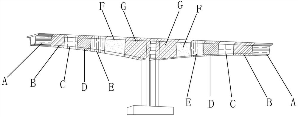
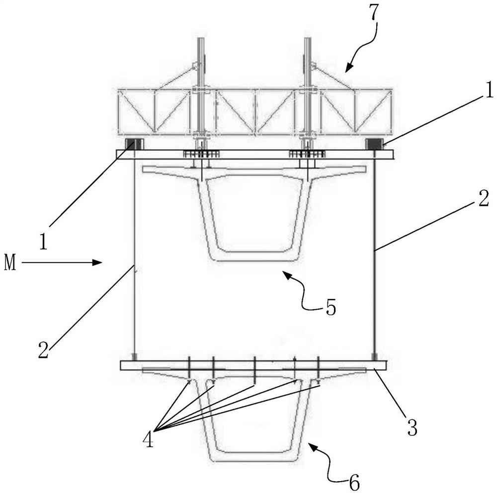
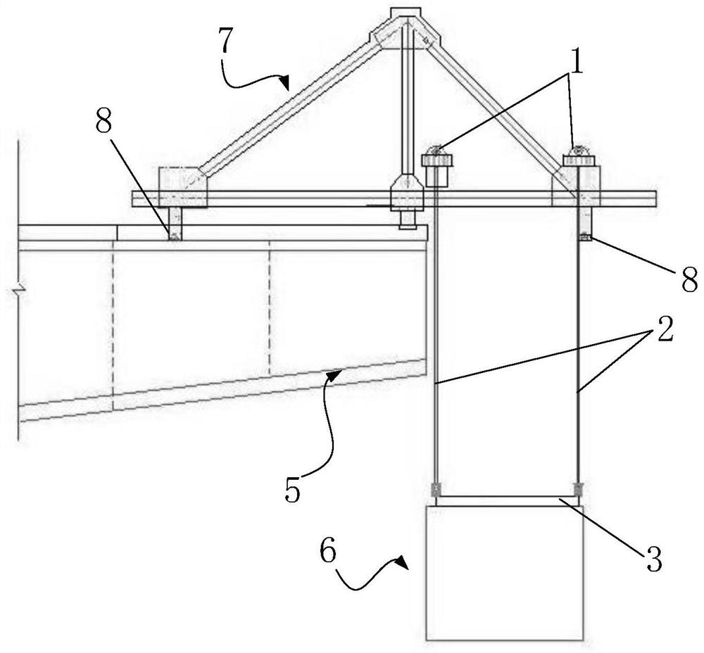
[0069] like Figure 1 to Figure 6 As shown, the continuous beam section prefabricated assembly method includes the following steps:

[0070] Step 1. Set the cast-in-place continuous section on the top of the main pier to meet the installation of segmental assembly and hoisting equipment. The length of the cast-in-place continuous section is based on the design shape of the continuous beam. Standard segment length on both sides;

[0071] Step 2, combined with the design of tensioned anchor pier with prestressed long beam anchor cables, re-divide the standard section of prestressed continuous beam so that the tensioned anchor pier is close to the end of the standard section;

[0072] Step 3: According to the division of prestressed prefabricated simply supported beam segments, pouring is carried out on the adjustable prefabricated ped...


PUM


Abstract

The invention discloses a continuous beam segment prefabricating and assembling method. The method comprises the steps: 1, arranging a cast-in-place continuous segment at the pier top of a main pier; 2, carrying out re dividing by combining a continuous beam prestress full-length bundle anchor cable tensioning anchorage pier design; 3, dividing the prefabricated simply supported beam sections according to the prestress; 4, performing processing according to the shape and the length of the pier top continuous beam; 5, assembling the prefabricated segment hoisting equipment on the cast-in-place continuous segment; 6, performing hoisting section by section according to section arrangement; 7, hoisting the sections; and 8, measuring the strength of the concrete, penetrating and pulling an anchor cable, performing tensioning, grouting and anchoring, and completing system transformation. According to the continuous beam segment prefabricating and assembling method, traditional continuous beam cantilever pouring construction is adjusted to ground construction from high altitude, segment prefabricating of a beam body is conducted on a prefabricating field, then the beam body is transported to the field segment by segment and hoisted to a preset position in a cantilever progressive mode, and then prestress is applied to sequentially connect all segments into a whole; and finally, the mid-span wet joint is cast in place in a suspended formwork mode to complete beam body construction.

Description

technical field [0001] The invention relates to the technical field of continuous beam construction, in particular to a method for prefabricating and assembling continuous beam segments. Background technique [0002] Bridge engineering refers to the work process of bridge survey, design, construction, maintenance and verification, as well as the science and engineering technology to study this process. The development of bridge engineering mainly depends on the needs of transportation. Ancient bridges mainly used people and livestock to pass through, and the load was light. The longitudinal slope of the bridge deck could be steep, and even steps could be laid. Since the railway was completed, the load on the bridge has doubled, the slope and curve standards of the line are high, and the railway network needs to be built to increase economic benefits. Therefore, in order to cross larger and deeper rivers and canyons, bridges are forced to To the large-span development. [0...

Claims


Application Information

Patent Timeline
Patent Type & Authority Applications(China)
IPC IPC(8): E01D21/00E01D21/10
CPCE01D21/00E01D21/10
Inventor 朱广琼桑亮亮王辉张永宏王勇赵炳政刘志弘弥王刚任继伟吴浩孙得会刘泽旺马正军王帅
Owner SINOHYDRO ENG BUREAU 4
Why Eureka
Try Eureka