Sieve pore deviation checking device and checking method

A sieve hole and deviation technology, applied in the field of test sieves, can solve the problems of heavy work and low efficiency, and achieve the effects of simple maintenance, avoiding cumbersome operations and convenient operation.

Inactive Publication Date: 2021-04-06
JIANYAN DETECTION GRP CO LTD
View PDF16 Cites 0 Cited by
  • Summary
  • Abstract
  • Description
  • Claims
  • Application Information

AI Technical Summary

Problems solved by technology

[0004] The purpose of the present invention is to provide a screen deviation check device and check method, aiming

Method used


Image

  • Sieve pore deviation checking device and checking method
  • Sieve pore deviation checking device and checking method
  • Sieve pore deviation checking device and checking method

Examples


Embodiment 1

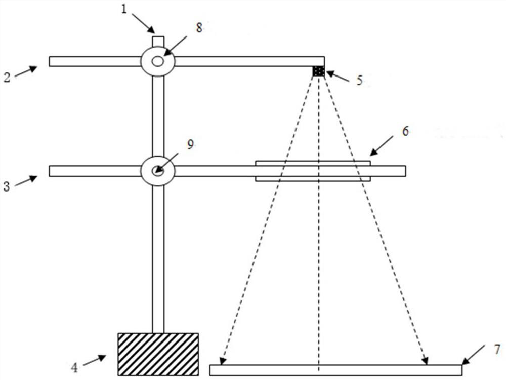
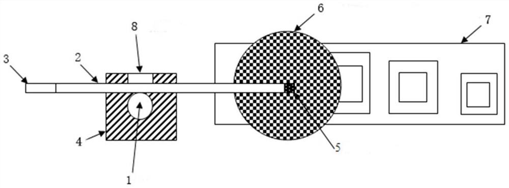
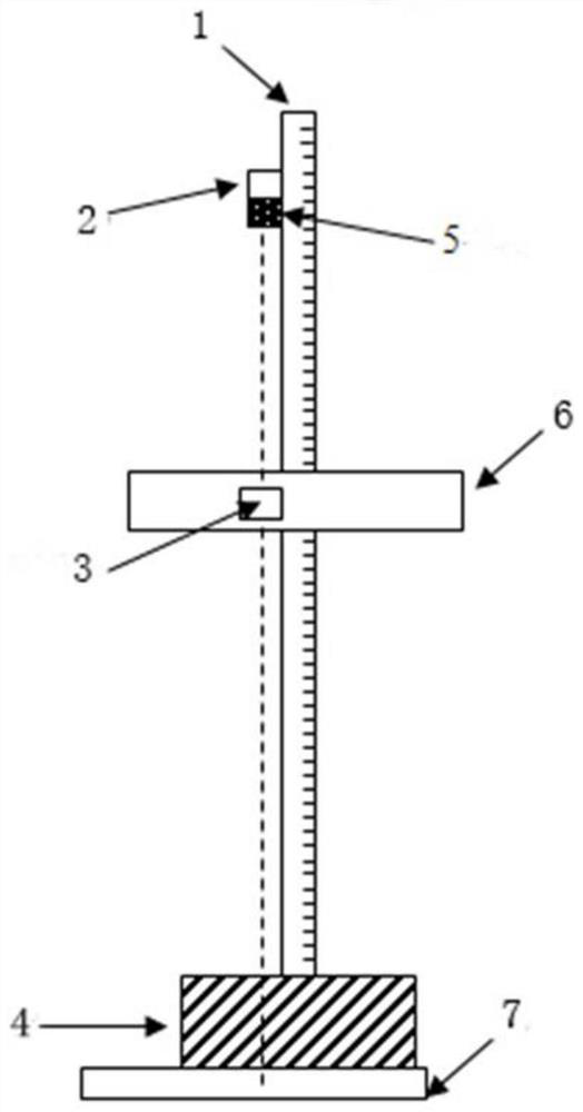
[0034] Such as Figure 1 to Figure 6c As shown, the present embodiment provides a sieve hole deviation checking device, including: a column 1 vertically installed on a base 4 , an adjustable bracket, a size deviation standard plate 7 and a light source 5 . Wherein, the adjustable bracket includes an upper bracket 2 and a lower bracket 3, both of which are movably installed on the column 1, and can be adjusted front and rear, left and right, up and down relative to the column 1. The light source 5 is installed on the upper bracket 2, the test sieve 6 is installed on the lower bracket 3, and the size deviation standard plate 7 includes a base plate 10 located below the lower bracket 3, on which a zigzag pattern 11 / 14 is drawn. The light source 5 emits projection light, which passes through the test sieve 6 and is projected onto the bottom plate 10 .

[0035] When testing the test sieve 6, the test sieve 6 to be tested is installed on the lower bracket 3, and the upper bracket 2...

Embodiment 2

[0049] Such as Figure 1 to Figure 6c As shown, the present embodiment provides a verification method for detecting the test sieve 6, comprising the following steps:

[0050] Assemble the above-mentioned sieve hole deviation checking device, in order to facilitate sliding, the upper bracket 2 and the lower bracket 3 can be properly coated with lubricating oil.

[0051] According to the size of the screen mesh of the test sieve 6 to be tested, the upper bracket 2 is adjusted to be extended to a sufficient length so that the projected light can be irradiated vertically to any sieve hole, and then the upper bracket 2 is fixed.

[0052] Fix the test sieve 6 to be tested on the installation position of the lower bracket 3 and ensure it is level, select any sieve hole to align with the projection light source 5, then fix the extension distance of the lower bracket 3, and adjust the longitudinal position of the lower bracket 3 so that the sieve to be tested The projection of the hol...

Embodiment 3

[0068] Such as Figure 1 to Figure 4 ,as well as Figure 6a , Figure 6b , Figure 6c As shown, the basic size L is selected in this embodiment 0 = 25mm, metal perforated plate test sieve 6 with permissible size deviation of sieve hole w=1.25mm, the shape of the sieve hole is square, and the diameter of the sieve is 400mm. The specific inspection is carried out according to the following steps:

[0069] a. After assembling the equipment, extend the upper bracket 2 to about 300mm and tighten it, turn on the power of the projection light source 5, confirm that the light source 5 is turned on normally, and confirm that the height of the upper bracket 2 is L AC =380mm;

[0070] b. Fix the screen on the lower bracket 3 and tighten it, adjust the level with a level ruler, select the screen hole in the center area of ​​the screen, adjust the extension length of the lower bracket 3, and make the selected screen hole align with the projection light source 5; then adjust The upper ...


PUM


Abstract

The invention relates to the technical field of test sieves, and discloses a sieve pore deviation checking device and checking method, and the sieve pore deviation checking device comprises a vertical column which is vertically installed on a pedestal; an adjustable support which comprises an upper support and a lower support, wherein the upper support and the lower support are movably installed on the stand column and can be adjusted front and back, left and right and up and down relative to the stand column, and the test sieve is installed on the lower support; a dimensional deviation standard plate which comprises a bottom plate located below the lower support, wherein a concentric-square-shaped pattern is drawn on the bottom plate; and a light source which is arranged on the upper support. According to the sieve pore deviation checking device and checking method, any pore on the checked metal perforated plate test sieve can be ensured to be vertically aligned with the light source and projected to the concentric-square-shaped pattern drawn by the positive and negative deviation of the sieve pores, the conformity of the size deviation of the sieve pores can be quickly compared and judged, and tedious operation of reading after amplification is avoided.

Description

technical field [0001] The invention relates to the technical field of test sieves, in particular to a sieve hole deviation checking device and checking method. Background technique [0002] Metal perforated plate test sieves are mainly used for particle size classification and particle size detection of material particles, and are widely used in scientific research units, laboratories, inspections, etc. In the laboratory, inspection and analysis of production control are carried out. The test sieves must be inspected and appraised by the designated agency, and they are considered to be in compliance with the agreed test sieves, so as to ensure the accuracy of the test results. At present, the existing methods all use a 50-200 times large optical magnifier or microscope device for measurement. [0003] When the test sieve is calibrated, put the test sieve on the glass worktable of the universal tool microscope, take a sample part at random, and use the universal tool micro...

Claims


Application Information

Patent Timeline
IPC IPC(8): G01N15/02
CPCG01N15/0227
Inventor 陈浩兰扬华王振华林春升苏武王伟达
Owner JIANYAN DETECTION GRP CO LTD
Why Eureka
Try Eureka