Portable wing ultrasonic nondestructive flaw detection scanning equipment and mounting method

A non-destructive flaw detection and ultrasonic technology, which is used in material analysis, measurement devices, and instruments using sonic/ultrasonic/infrasonic waves, which can solve the problems of difficult operation, low detection efficiency, and time-consuming

Pending Publication Date: 2021-04-06
南昌市彦畅机电科技有限公司 +1
View PDF0 Cites 2 Cited by
  • Summary
  • Abstract
  • Description
  • Claims
  • Application Information

AI Technical Summary

Problems solved by technology

At present, the flaw detection of the wing is to lift the wing to be tested to the tooling carrier and fix the wing through the fixing device on it. It can only be tested before the wing is installed on the aircraft. It is unrealistic to disassemble and lift the wing of the aircraft outside the site. The shortcomings of the existing technology are: difficult detection and low detection efficiency. The existing technology needs to fix the X-ray machine and the receiving board at a certain position, and then move the X-ray machine and the receiving board to the next point for detection after the detection is completed. , go round and round, it takes a lot of time, you need to change the position of the x-ray machine and the receiving plate many times, and you need to adjust the x-ray machine to be perpendicular to the surface of the workpiece, the operation is difficult, and the detection efficiency is low
Its defect is that the measured wings are all wings that have not been installed on the aircraft, and can only be detected before the wings are installed on the aircraft. If they are already installed on the fuselage, they cannot be measured by this method, and there are serious defects.

Method used


Image

  • Portable wing ultrasonic nondestructive flaw detection scanning equipment and mounting method
  • Portable wing ultrasonic nondestructive flaw detection scanning equipment and mounting method
  • Portable wing ultrasonic nondestructive flaw detection scanning equipment and mounting method

Examples


Embodiment 1

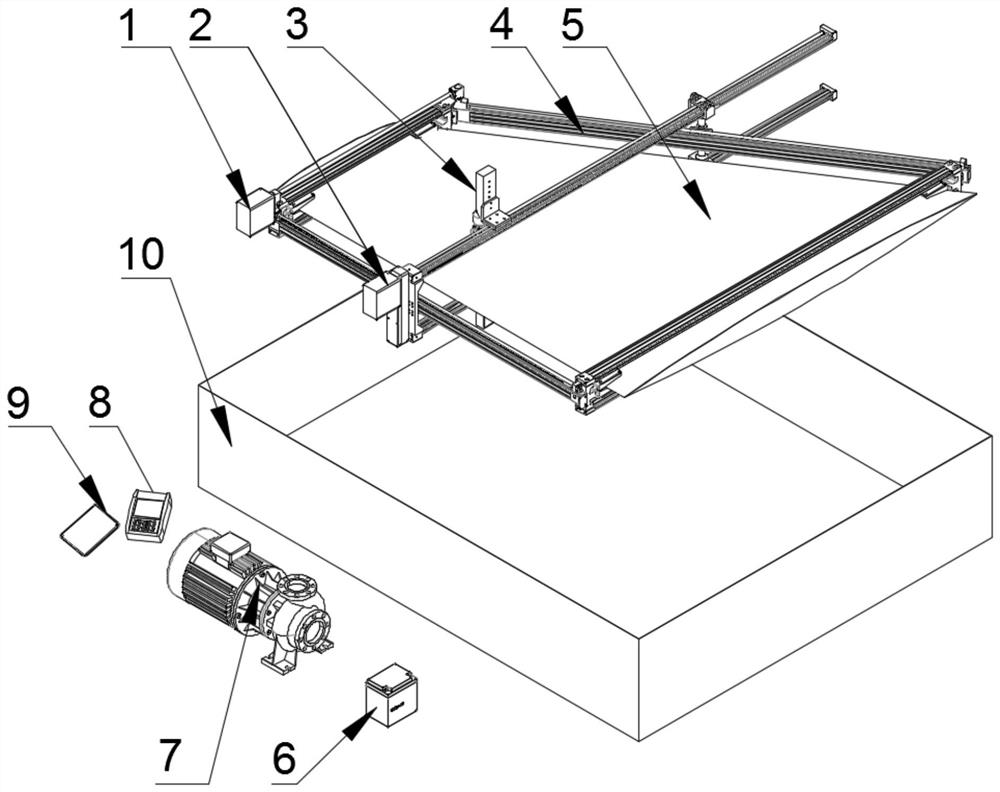
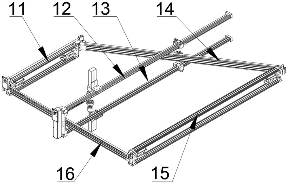
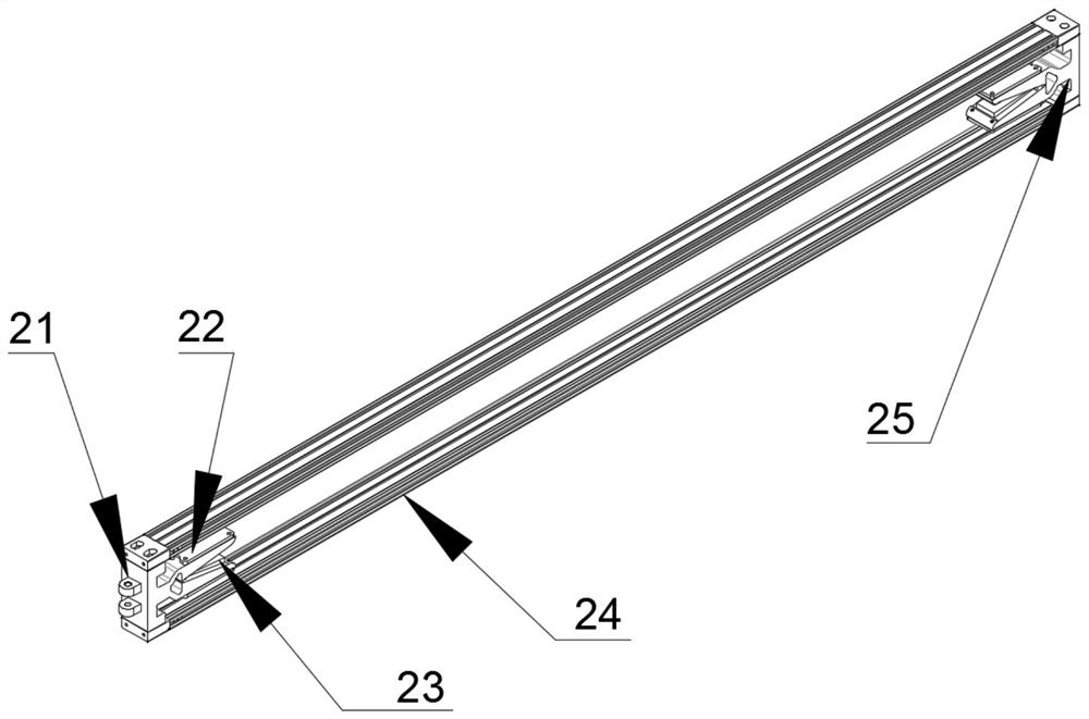
[0060] Embodiment 1, refer to Figure 1-Figure 6 and Figure 8, a portable wing ultrasonic non-destructive testing equipment, including a scanning fixture 4, an end effector 3, an ultrasonic flaw detector 8, a control panel 9, a mobile power supply 6 and a stepping motor, wherein: the scanning fixture 4 includes Short clamping link 11, upward Y-direction rail link 12, downward Y-direction guide rail link 13, X-direction inclined guide rail link 14, long clamping link 15 and X-direction short guide rail link 16, the short clip One end of the holding link 11 and the long clamping link 15 is fixedly provided with a first clamping fixture 21, and the other end of the short clamping link 11 and the long clamping link 15 is fixedly provided with a second clip. One end of the X-direction inclined guide rail connecting rod 14 and the X-direction short guide rail connecting rod 16 is fixedly provided with a first pin ear joint 52, and the X-direction inclined guide rail connecting rod...


PUM


Abstract

The invention relates to portable wing ultrasonic nondestructive flaw detection scanning equipment and a mounting method. The ultrasonic flaw detection equipment comprises a scanning fixing frame, end actuators, an ultrasonic flaw detector, a control panel, a mobile power source and a stepping motor, wherein the two ultrasonic end actuators are fixedly installed on the scanning fixing frame through bolt connection, and the upper portion and the lower portion of the scanning fixing frame are each provided with one end actuator; the ultrasonic flaw detector is connected with an ultrasonic probe on the end effector through a probe wire, and the control platform is connected with the stepping motor through a control wire; the stepping motor is installed on the scanning fixing frame through the motor connecting piece and the motor fixing connecting piece, the mobile power supply is used for supplying power, detection problems of multiple directions, multiple detection types and multiple key points of a large detection object are solved, and full-automatic detection of wings installed on an airplane is facilitated through the detachable tool frame.

Description

technical field [0001] The invention relates to the technical field of wing flaw detection and scanning devices, in particular to a portable wing ultrasonic non-destructive flaw detection and scanning equipment. Background technique [0002] With the continuous increase of the application proportion of composite materials in aerospace structures, in order to ensure flight safety, monitoring the internal quality of composite structures has received more and more attention. Therefore, the non-destructive testing technology of aerospace composite materials is also increasingly used in the whole process of forming, assembling, testing, maintaining and using aerospace composite materials. Non-destructive testing is the use of non-destructive means, using sound, light, electricity, heat, magnetism, and radiation technologies to detect defects and positions that affect the use of materials, internal voids, magazines, cracks, and delaminations. At present, the flaw detection of the...

Claims


Application Information

Patent Timeline
Patent Type & Authority Applications(China)
IPC IPC(8): G01N29/265
CPCG01N29/265G01N2291/0231G01N2291/0289G01N2291/2694
Inventor 袁磊肖树坤殷晓芳杨光金超宁王乐浩曾卓毅付美娟陈鸣晖
Owner 南昌市彦畅机电科技有限公司
Why Eureka
Try Eureka