

A cooling device for a transformer and its working method
A cooling device and transformer technology, applied in the field of transformers, can solve problems such as poor cooling effect, difficulty in ensuring air flow, and accelerated cooling
Active Publication Date: 2022-05-31
安徽晶飞科技有限公司
View PDF0 Cites 0 Cited by
- Summary
- Abstract
- Description
- Claims
- Application Information
AI Technical Summary
Problems solved by technology
[0004] Aiming at the deficiencies of the prior art, the present invention provides a cooling device for a transformer, which solves the problem of cooling the inside of the transformer through a fan, but it is difficult to ensure the flow of all the internal air, and it is difficult to speed up the cooling through the air flow in some positions, and the cooling effect is not good. good question
Method used
View moreImage
Smart ImageViewing Examples

Examples
Embodiment Construction
[0029] At the same time, the content not described in detail in this specification belongs to the prior art known to those skilled in the art.
Login to View More PUM
 Abstract
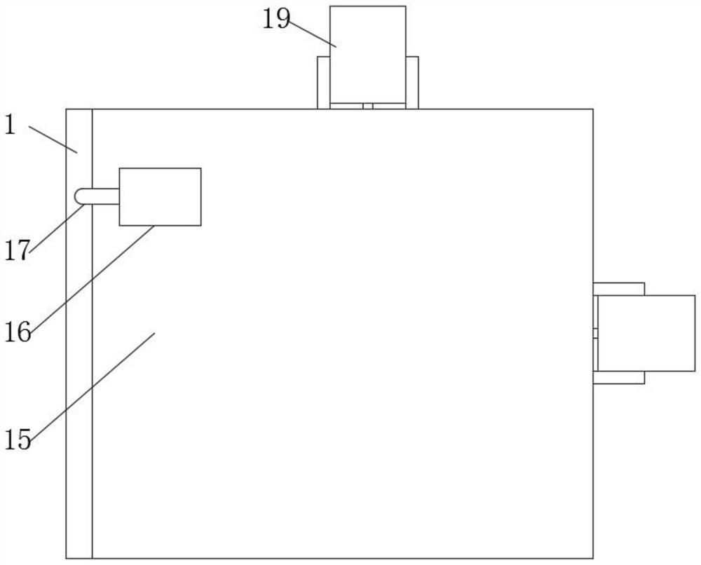
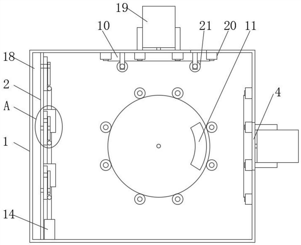
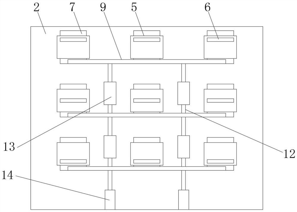
The invention discloses a cooling device for a transformer, which comprises a box body. A vertical plate is fixedly connected to the inner cavity of the box body, and an air intake slot is opened on the side of the vertical plate. The invention relates to the technical field of transformers. The transformer uses a cooling device, and the same row of slides is connected by a cross bar to ensure synchronous movement. The movement of the slides drives the second slot to move. By changing the position of the second slot, the corresponding position of the first slot and the intake air can be adjusted. The connection of the grooves, the air enters the box through different heights, and multiple air outlet grooves are set at different positions. When the rotating plate rotates, the position of the third through groove is driven to change when the rotating plate rotates. When the third through groove and the air outlet groove are connected , the air in the box is discharged from the connecting position. By rotating the rotating plate, the air outlet position can be changed. By changing the air intake position and the air outlet position, the air flow path in the box can be changed to ensure that all the air in the box will flow and ensure the cooling effect.
Description
A cooling device for transformer and its working method technical field [0001] The present invention relates to the technical field of transformers, in particular to a cooling device for a transformer and a working method thereof. Background technique [0002] Transformer refers to a device that uses the principle of electromagnetic induction to change AC voltage. transformer During operation, due to the existence of iron loss and copper loss, these losses will be converted into heat energy and radiated outward, causing The transformer continues to heat up and the temperature rises, and the heat dissipation of the transformer is not good, which will cause the temperature of the transformer to rise, exceeding the allowable limit of the transformer. The temperature rise level will reduce the service life of the transformer in light, and damage the transformer in severe cases. Therefore, in order to ensure the heat dissipation of large transformers Good, some cooling met...
Claims
Login to View More Application Information
Patent Timeline
 Patent Type & AuthorityPatents(China)
IPC IPC(8): H01F27/08
CPCH01F27/085
Inventor刁超高超何慧义任其飞张磊张明红束文静
Owner安徽晶飞科技有限公司