Inter-plant weeding and fertilizing machine
A fertilizer applicator and plant-to-plant technology, applied in fertilization devices, soil preparation machines, fertilizer distributors, etc., can solve problems such as difficult data processing
- Summary
- Abstract
- Description
- Claims
- Application Information
AI Technical Summary
Problems solved by technology
Method used
Image

Examples
Embodiment Construction
[0028] The present invention will be further described below in conjunction with the accompanying drawings.
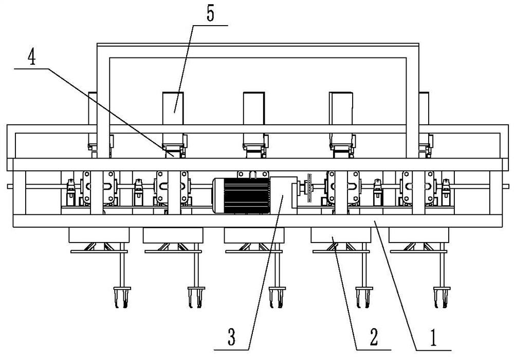
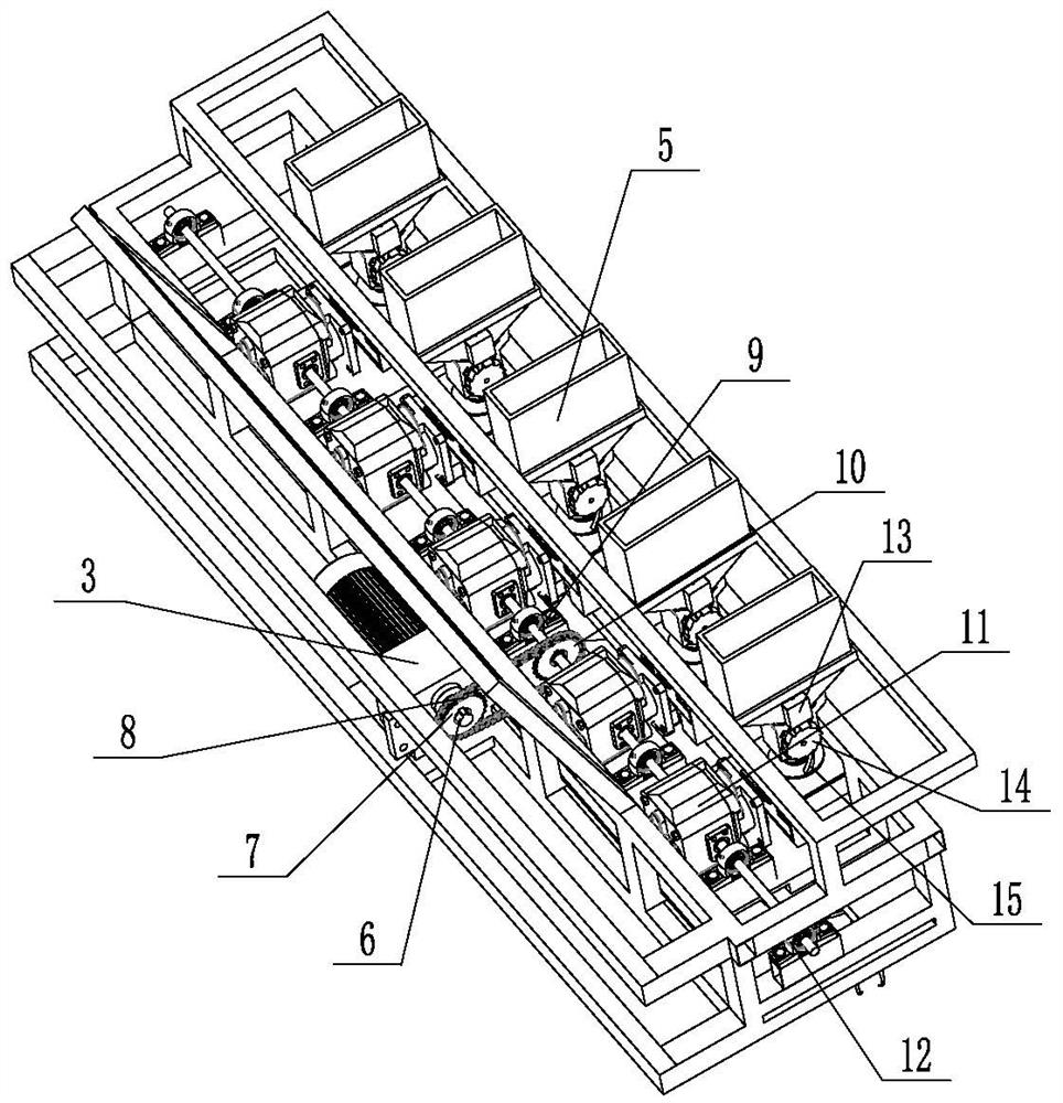
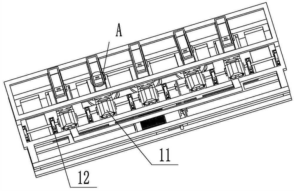
[0029] Such as Figure 1~14 A kind of inter-row weeding and fertilizing machine shown includes a frame 1, and several weeding mechanisms 2 are arranged on the length direction of the frame 1. The weeding mechanism 2 includes a fixed cover 213 and is rotatably connected to the frame 1 and vertically The transmission shaft 206 that is set straightly, the bottom of transmission shaft 206 is connected with turntable 205, and turntable 205 is just sleeved on the bottom of transmission shaft 206, and the lower side of transmission shaft 206 is fixedly connected with fixed plate 215, and the center of fixed plate 215 is provided with convenient and transmission shaft. 206 to connect the fixed holes 221, the fixed plate 215 outside the transmission shaft 206 is arranged with several connecting holes 220, the fixed plate 215 is fixedly connected with the turntable 205, and the ...
PUM
 Abstract
Description
Claims
Application Information
PatSnap Eureka turns technology decisions into work you can execute. Powered by our Innovation Knowledge Graph, it runs expert workflows across engineering, life sciences, materials and intellectual property. Get your review-ready output in minutes.


