Eureka AIR delivers breakthrough ideas for toughest innovation challenges, trusted by R&D personnel around the world.

Substantially flat, aperture coupled antenna element

An antenna unit and aperture coupling technology, which is applied to antennas, slot antennas, resonant antennas, etc., can solve the problems of design technology and manufacturing disorder, cost increase, etc.

Inactive Publication Date: 2003-10-29
INTEL CORP
View PDF1 Cites 0 Cited by
  • Summary
  • Abstract
  • Description
  • Claims
  • Application Information

AI Technical Summary

Problems solved by technology

These measures involve significant complication in terms of design technology and manufacturing or an increase in expense due to the two separate dielectric boards with associated feeder networks

Method used


Image

  • Substantially flat, aperture coupled antenna element
  • Substantially flat, aperture coupled antenna element
  • Substantially flat, aperture coupled antenna element

Examples


Embodiment Construction

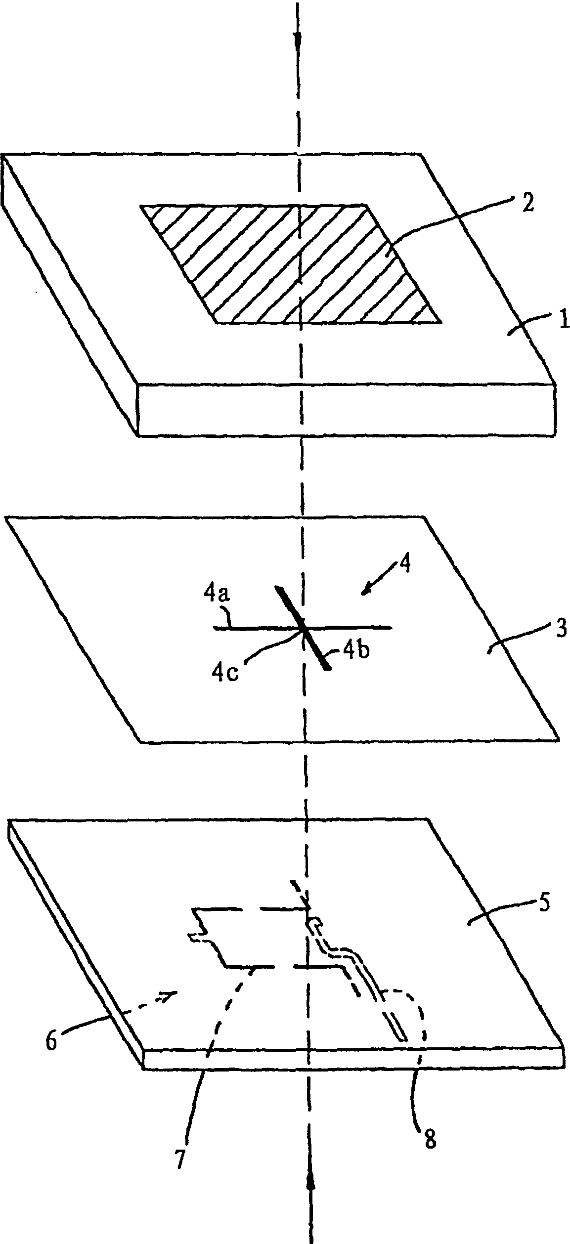
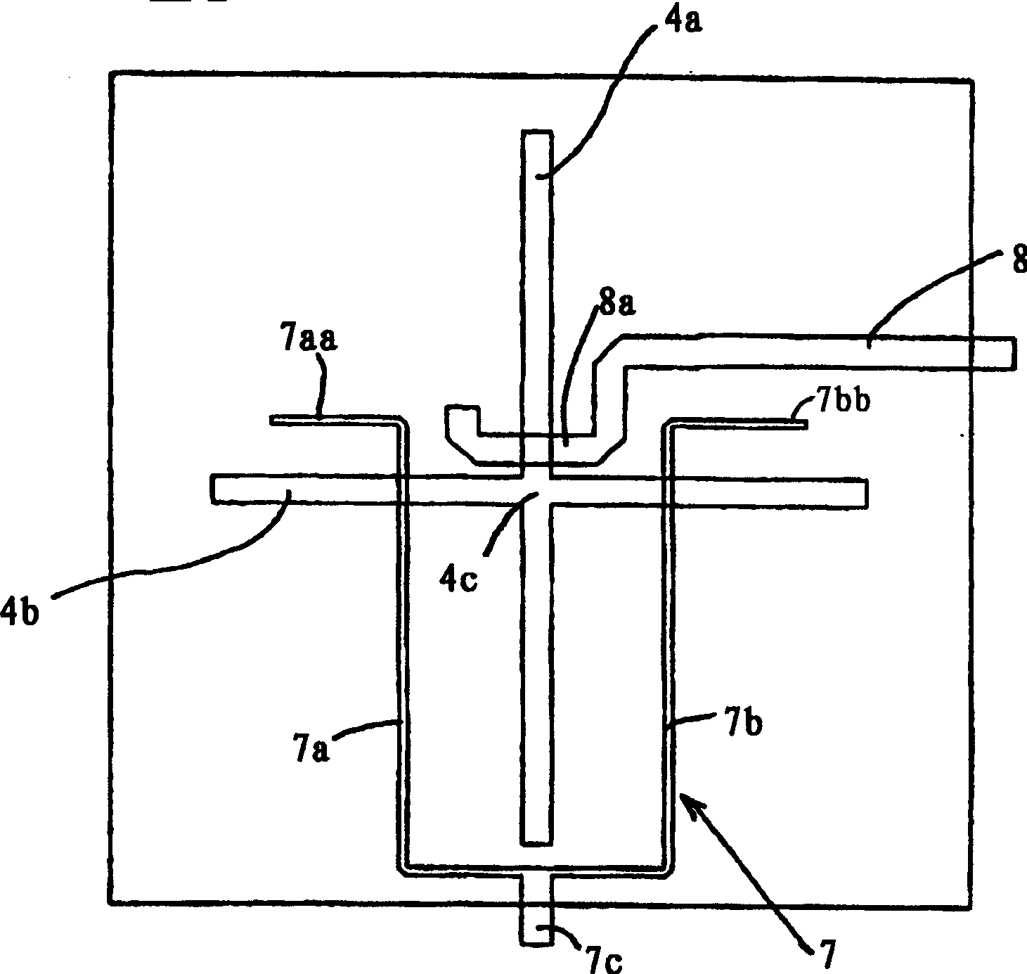
[0012] figure 1 The antenna element shown schematically in contains a multilayer structure. This structure includes a relatively thick upper dielectric layer 1, on which a rectangular plate 2 is provided, which constitutes the radiating part of the antenna unit; Conductive ground plane layer 3 of the aperture 4, and a thinner plate or substrate 5 of low dielectric, with a feed network 6 in a planar arrangement on the underside of the substrate 5, i.e. on the side away from the cross-shaped aperture 4, In order to ensure that there is a distance corresponding to the thickness of the plate 5 between the network and the cross-shaped apertures.

[0013] In the example shown, the upper layer 1 has a thickness of approximately 15 mm and is made of Rohacell foam. Plate 2 is made of aluminum foil with a thickness of 50 μm and a size of 54×50 mm.

[0014] Centrally under the plate 2 is a cross-shaped aperture 4 consisting of two mutually perpendicular slots 4a, 4b intersecting at a ...


PUM


Abstract

A rather flat aperture-coupled antenna element consisting of a multilayer structure with a radiating plate (2) arranged on a dielectric layer (1), one with two intersecting slots ( 4a, 4b) a conductive ground plane layer (3) with a cross-shaped aperture (4) in the center of the board, and a dielectric board equipped with a feed network (6). The feed network is used to feed microwave energy to the plate through the feed elements (7, 8) and the cross-shaped aperture (4), so that the plate can generate a dual-polarized microwave beam from This antenna element propagates out. The multilayer structure comprises a single dielectric plate (5) equipped with a planar feed network (6). The feed network has a first feed element (7) with a pair of feed lines extending symmetrically on each side of the aperture center (4c), and with a pair of feed lines located asymmetrically on one side of said aperture center and A second feed element (8) of a single feed line that does not intersect said first feed element. The orientation and dimensions of the two feed elements (8, 7) are chosen to excite each of the slots (4a, 4b) respectively from the corresponding microwave channel.

Description

technical field [0001] The invention relates to an antenna unit, especially an antenna unit used in a base station antenna for mobile communication. Background technique [0002] Such antenna units are previously known from, for example, US patent specification No. 5,030,961 (Tsao) and an article (Yamazaki) on pages 1814-1815 of the magazine Electronic Letters, Vol. 30, No. 22, 1994. In order to obtain dual polarization with a fairly wide frequency bandwidth and a high degree of isolation between the two channels, it has been necessary to install an air bridge in a planar feed network (as proposed by Tsao), or to configure two Separate different media plates (as proposed by yamazaki). These measures involve considerable complication in design and production or an increase in expense due to the two separate dielectric boards with the associated power supply network. Contents of the invention [0003] Against this background, the main object of the present invention is to ...

Claims


Application Information

Patent Timeline
Patent Type & Authority Patents(China)
IPC IPC(8): H01Q13/10H01Q1/38H01Q5/00H01Q9/04
CPCH01Q9/0435H01Q9/0457H01Q13/106
Inventor 比乔恩·林德马克
Owner INTEL CORP
Why Eureka
Eureka Blog
Learn More