Dedusting device for environment-friendly machinery

A technology of dust removal device and machinery, applied in the direction of using liquid separating agent, filtration loop, filtration separation, etc., can solve the problems of inability to sense garbage and impurities, inconvenient maintenance, and the flying of particulate matter.

Active Publication Date: 2021-04-09
鄂尔多斯市锦隆建筑安装有限责任公司
View PDF6 Cites 4 Cited by
  • Summary
  • Abstract
  • Description
  • Claims
  • Application Information

AI Technical Summary

Problems solved by technology

[0003] In the prior art, the existing sprinkler dedusting device will be equipped with a collection device to collect water and particulate matter, avoiding the water and particulate matter from falling on the ground, and avoiding the problem that the particulate matter falls on all sides and dries before flying up. Recycling and reuse of water resources is realized, avoiding the waste of water resources, but the filter screen device in the collection device needs regular maintenance, because there is no corresponding sensing device, it is impossible to sense the garbage and impurities in the filter device, and the number of maintenance Many, inconvenient maintenance

Method used


Image

  • Dedusting device for environment-friendly machinery
  • Dedusting device for environment-friendly machinery
  • Dedusting device for environment-friendly machinery

Examples


Embodiment 1

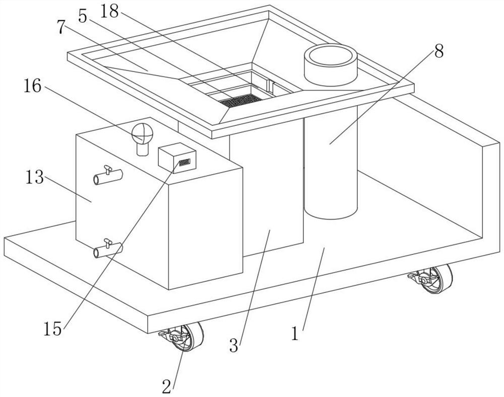
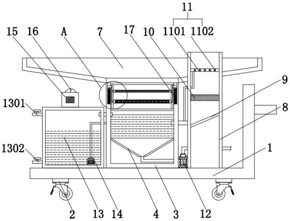
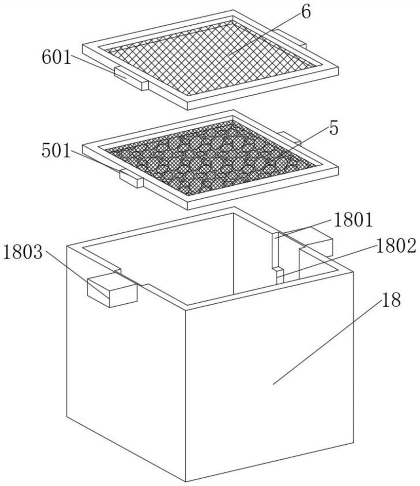
[0030] see Figure 1-4 , a dust removal device for environmental protection machinery, comprising a bottom plate 1, the four corners of the bottom of the bottom plate 1 are fixedly connected with universal wheels 2, the top of the bottom plate 1 is fixedly connected with a sedimentation tank 3, and the top of the sedimentation tank 3 is fixedly connected with a water collection frame 7 , the inner wall of the sedimentation tank 3 is fixedly connected with a funnel 4, the top of the bottom plate 1 is fixedly connected with a dredge pump 12, the left end of the dredge pump 12 is connected with a connecting pipe, and the left end of the connecting pipe runs through the sedimentation tank 3 and is connected with the bottom of the funnel 4 The inner wall of the settling box 3 is clamped with a square frame 18, the inner wall of the square frame 18 is clamped with a filter device 5, the inner wall of the square frame 18 is clamped with a filter plate 6 above the filter device 5, and ...

Embodiment 2

[0039] like Figure 5 to Figure 6 As shown, in this example,

[0040] The top of the circular tube 8 is provided with a charge loading device 19, and the charge loading device 19 includes a cathode discharge plate 19-1 and an anode discharge plate 19-2 symmetrically arranged on the inner wall of the circular tube 8. The discharge plate 19-1 is connected to a high-voltage power supply, and the anode discharge plate 19-2 is grounded,

[0041] The upper surface of the water collection frame 7 is provided with several rows of uniformly distributed water collection arrays 20 extending toward the settling tank 3. The water collection arrays 20 include a number of vertically arranged inverted V-shaped water collection plates. The water collecting plate is made of metal, and the adjacent water collecting arrays 20 are respectively connected to the positive pole and the negative pole of the power supply,

[0042] The lower bottom surface of the water collection frame 7 is provided wi...

Embodiment 3

[0051] like Figure 7 As shown, in this example,

[0052] Openings 302 are provided on the front and rear sides of the upper part of the sedimentation tank 3, and the opening 302 on the front side is provided with a flip cover 303, and the bottom plate 1 on the rear side of the sedimentation tank 3 is provided with a replacement device 22. The inner walls of the left and right sides of the settling box 3 are provided with a second chute 304 horizontally, the left and right side walls of the middle part of the settling box 3 are provided with lifting devices 23, the square frame 18 is provided with a handle 1804 on the front side, and the flip cover 303 inside is provided with a number of limit blocks 305, the replacement device 22 includes a box 22-1, the bottom of the box 22-1 is provided with an electronically controlled lifter 22-2, and the electronically controlled lifter 22 The top of -2 is provided with a bearing plate 22-3, and the electric control push rod 22-4 is arr...


PUM


Abstract

The invention discloses a dust removal device for environment-friendly machinery, and belongs to the technical field of dust removal of environment-friendly machinery. The dust removal device comprises a bottom plate, wherein universal wheels are fixedly connected to four corners of the bottom of the bottom plate, a settling tank is fixedly connected to the top of the bottom plate, a water collecting frame is fixedly connected to the top of the settling tank, the inner wall of the settling tank is fixedly connected with a funnel, the top of the bottom plate is fixedly connected with a mud sucking pump, and the left end of the mud sucking pump is communicated with a connecting pipe. According to the scheme, by arranging a sensing device, the overall weight of the square frame can be detected, and when the filtering efficiency of a filtering plate and a filtering device in the square frame is reduced or more impurities are accumulated, detection can be performed in real time through a warning lamp, so that the number of times of observation and disassembly by an operator is reduced, and the labor intensity of maintenance is reduced; and the square frame is more convenient to disassemble through the design of a first clamping groove and a first clamping block, so that the disassembly time is shortened.

Description

technical field [0001] The invention relates to the technical field of dust removal for environmental protection machinery, more specifically, to a dust removal device for environmental protection machinery. Background technique [0002] At present, my country's economic construction is developing rapidly, people's living standards are constantly improving, and society's requirements for environmental protection are getting higher and higher. In some production workshops or laboratories and other workplaces, a large amount of dust particles are generated indoors during the work process. Pollution to the air. The existence of these dust particles will affect the health and working conditions of the staff. Therefore, it is essential to equip the production workshop and other indoors with spray dust removal equipment. Spray dust removal equipment refers to the dust removal equipment in the air. The equipment that separates particles from the air reduces the dust content in the ai...

Claims


Application Information

Patent Timeline
Patent Type & Authority Applications(China)
IPC IPC(8): B01D47/06B01D36/04
CPCB01D47/06B01D36/04
Inventor 季朋鹏
Owner 鄂尔多斯市锦隆建筑安装有限责任公司
Why Eureka
Try Eureka