Pre-cooling device of concrete aggregate

A concrete aggregate and cooling device technology, which is applied in the direction of clay preparation device, mixing operation control device, pretreatment control, etc., can solve the problems of slow heat dissipation and low precooling efficiency

Active Publication Date: 2021-04-09
CHINA CONSTR SECOND ENG BUREAU LTD
View PDF7 Cites 0 Cited by
  • Summary
  • Abstract
  • Description
  • Claims
  • Application Information

AI Technical Summary

Problems solved by technology

The present invention achieves the effect of a concrete aggregate pre-cooling device that can cool concrete aggregates in multiple ways to maximize efficiency, and can recycle water for use. Although this patent can pre-cool aggregates, ...

Method used


Image

  • Pre-cooling device of concrete aggregate
  • Pre-cooling device of concrete aggregate
  • Pre-cooling device of concrete aggregate

Examples


Embodiment 1

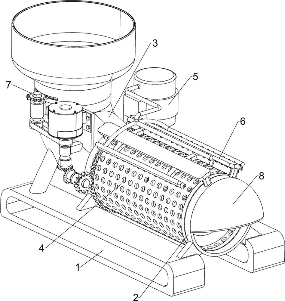
[0024] A concrete aggregate pre-cooling device, such as Figure 1-3 As shown, it includes a base 1, a mounting frame 2, a feed pipe 3, a rotating mechanism 4, a pressurizing mechanism 5 and a water spray structure 6, the left and right sides of the top of the base 1 are connected with the mounting frame 2, and the left side of the top of the base 1 A feed pipe 3 is connected, a rotating mechanism 4 is installed between the mounting frame 2 and the feeding pipe 3, a pressurizing mechanism 5 is installed on the top of the base 1, and the pressurizing mechanism 5 is connected to the rotating mechanism 4 through transmission, and the mounting frame 2 is installed with The water spray structure 6 is connected with the pressurizing mechanism 5 .

[0025] The rotating mechanism 4 includes a leaking screen cylinder 41, a screw pusher block 42, a first rack ring 43, a first gear 44, a fixed mount 45, a first bevel gear 46, a second bevel gear 47 and a servo motor 48, two installations ...

Embodiment 2

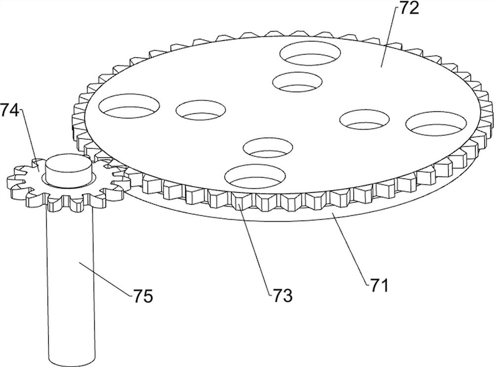
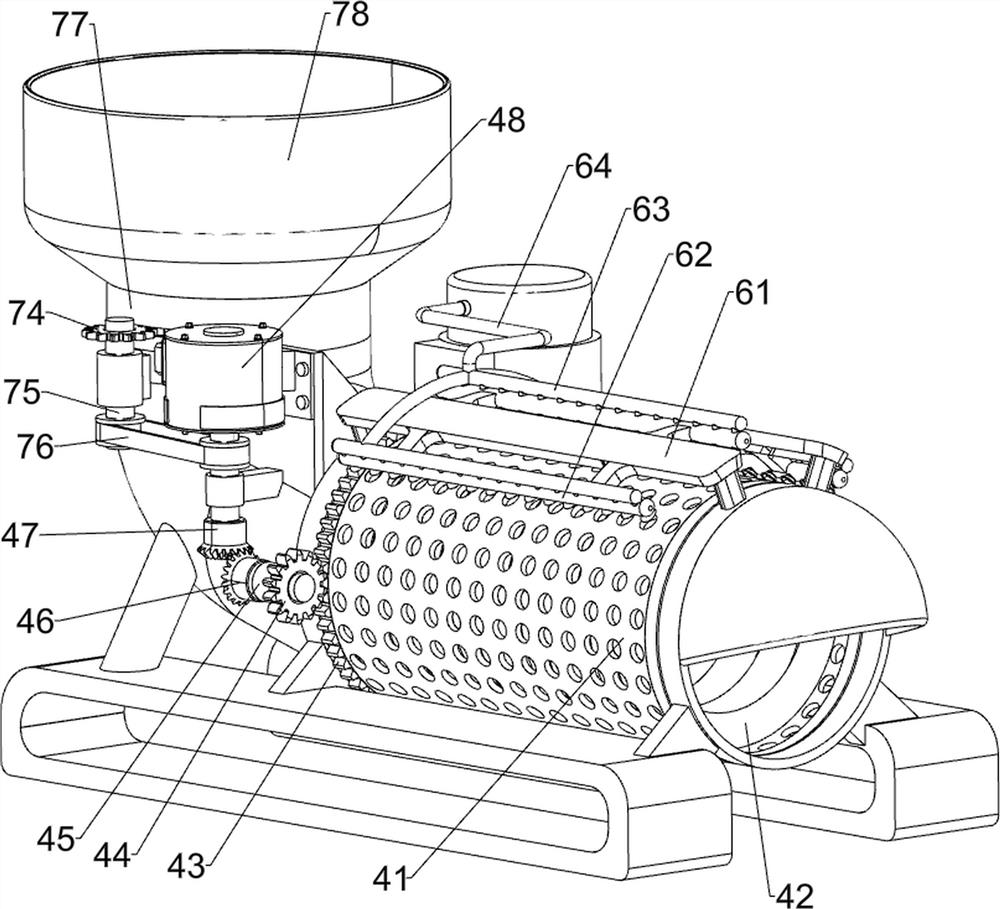
[0030] On the basis of Example 1, such as Figure 1 to Figure 4As shown, it also includes a feed amount control mechanism 7, and the feed amount control mechanism 7 includes a fixed perforated plate 71, a rotating perforated plate 72, a second rack ring 73, a third gear 74, a transmission shaft 75, a Two drive belt sets 76, shell 77 and material storage box 78, the upper part of feeding pipeline 3 front side outer walls is connected with transmission shaft 75 in a rotational manner, is connected with the 3rd gear 74 on the transmission shaft 75, transmission shaft 75 and servomotor 48 A second drive belt set 76 is connected between the output shafts, a casing 77 is connected to the top of the feed pipe 3, a fixed perforated plate 71 is connected inside the casing 77, and a rotary perforated plate 72 is connected to the top of the fixed perforated plate 71 in a rotatable manner. A second rack ring 73 is connected to the outer wall of the rotating perforated plate 72 , the secon...


PUM


Abstract

The invention relates to a cooling device, in particular to a pre-cooling device of concrete aggregate. The pre-cooling device of the concrete aggregate enables aggregate to move, can increase gaps among the aggregate and improve the pre-cooling efficiency. The pre-cooling device of the concrete aggregate comprises a base, a feeding pipeline, a rotating mechanism and a pressurizing mechanism, wherein the two sides of the upper side of the base are both connected with mounting frames, the side, close to the mounting frame on one side, of the base is connected with the feeding pipeline, the rotating mechanism is mounted between the mounting frame and the feeding pipeline, the pressurizing mechanism is mounted on the base, and the pressurizing mechanism is in transmission connection with the rotating mechanism. The aggregate can be rotated and moved rightwards through the rotating mechanism, so that the purposes of moving the aggregate and increasing the gaps among the aggregate are achieved; cold water can be sprayed onto the aggregate through cooperation of the pressurizing mechanism and a water spraying structure, then the aggregate can be pre-cooled, and the pre-cooling efficiency can be improved.

Description

technical field [0001] The invention relates to a cooling device, in particular to a concrete aggregate pre-cooling device. Background technique [0002] Pre-cooling aggregate refers to the process of cooling the concrete aggregate before entering the mixer to reduce the calorific value of the concrete mixture. [0003] After searching, the patent publication number is: CN107310012A patent, which discloses a concrete aggregate pre-cooling device, including a base, a bracket, a cooling box, an ice cooling device, a blowing cooling device, etc., a bracket is provided on the left side of the top of the base, and a bracket is installed on the top of the bracket. There is an ice cooling device, a cooling box is installed on the right side of the ice cooling device, a first feeding hopper is arranged in the middle of the top of the cooling box, a first opening is opened on the left wall of the cooling box, a blowing cooling device is installed on the upper part of the right wall o...

Claims


Application Information

Patent Timeline
IPC IPC(8): B28C7/00
CPCB28C7/0038Y02W30/91
Inventor 肖九长
Owner CHINA CONSTR SECOND ENG BUREAU LTD
Why Eureka
Try Eureka