Rubber production equipment

A technology for production equipment and rubber, which is applied in the direction of cleaning hollow objects, chemical instruments and methods, cleaning methods and utensils, etc., can solve problems such as untimely cleaning, waste of resources, and difficulty in cleaning, so as to facilitate subsequent use and reduce power Use, spray fast and even effect

Inactive Publication Date: 2021-04-09
余启洪
View PDF14 Cites 1 Cited by
  • Summary
  • Abstract
  • Description
  • Claims
  • Application Information

AI Technical Summary

Problems solved by technology

[0005] Aiming at the deficiencies of the prior art, the present invention provides a kind of rubber production equipment, which solves the problem that it needs to be manually added, which is time-consuming and labor-intensive. When encountering viscous raw materials, the mixing is more difficult and prone to uneven mixing. The situation makes the rubber quality low, which affects the later use, and the viscous raw material will stick to the inner wall of the equipment, which cannot be cleaned in time, which increases the resistance when mixing materials, and is not easy to clean. It also causes waste of resources and reduces the performance of the equipment. question

Method used


Image

  • Rubber production equipment
  • Rubber production equipment
  • Rubber production equipment

Examples


Embodiment example 1

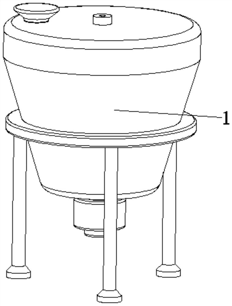
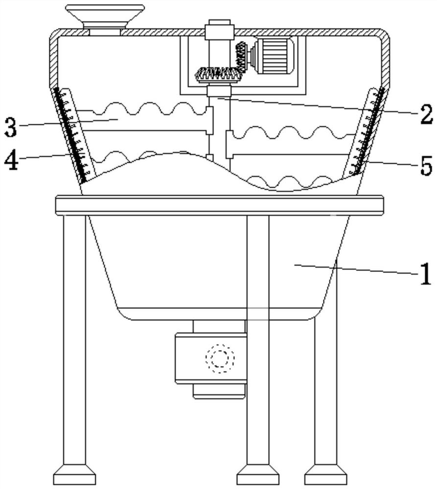
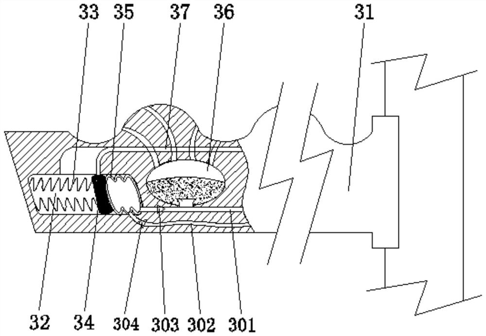
[0034] see Figure 1-8, the present invention provides a technical solution: a rubber production equipment, including a body 1, the body 1 is provided with a rotating shaft 2, a stirring device 3, a wall scraping device 4, and a magnetic strip 5, and the rotating shaft 2 is rotatably connected to the central position of the inner wall of the body 1, The stirring device 3 is fixed on the surface of the shaft 2, the wall scraping device 4 is fixed on the end of the stirring device 3 and is located at the inner wall of the body 1, the magnetic strip 5 is arranged inside the body 1, and the stirring device 3 is provided with a stirrer 31, an inner cavity 32. Return spring 33, magnetic block 34, elastic air bag 35, storage chamber 36, spray device 37, the inner cavity 32 is set inside the stirrer 31 and is located at the end, and the return spring 33 is fixed on the inner cavity 32 One side of the inner wall, the magnetic block 34 is fixed on the top of the return spring 33, the el...

Embodiment example 2

[0038] The wall scraping device 4 is provided with a scraper device 41, a rectangular notch 42, and a cutter 43. The rectangular notch 42 is set on one side of the surface of the scraper device 41, and the cutter 43 is fixed on the surface of the scraper device 41 and is positioned at the side of the rectangular notch 42. Position, through its own rotation, the viscous material can be scraped off smoothly, saving time and effort, and the rectangular notch 42 reduces the force-bearing area during scraping, making the resistance smaller. At the same time, during the scraping process, the cutter 43 Segment the viscous, further destroy the adhesion between the viscous, further reduce the resistance, and facilitate subsequent scraping.

[0039] The scraper device 41 is provided with a scraper body 411, a first arc-shaped plate 412, a second arc-shaped plate 413, an arc-shaped surface 414, and a row of holes 415. The first arc-shaped plate 412 and the second arc-shaped plate 413 are ...


PUM


Abstract

The invention discloses rubber production equipment, comprising a machine body. The machine body is provided with a rotating shaft, a stirring device, a wall scraping device and a magnetic strip; the stirring device is fixed to the surface of the shaft; the wall scraping device is fixed to the end of the stirring device and located on the inner wall of the machine body; the magnetic strip is arranged in the machine body; the inner cavity is formed in the stirrer and located at the end; the magnetic block is fixed to the top of a reset spring; the elastic air bag is arranged in the inner cavity and located at the magnetic block; the magnetic strip is arranged in the stirrer; and the spraying device is arranged in the stirrer and located at the top of an agent storage cavity. The invention relates to the technical field of rubber production. The rubber production equipment achieves the purposes of uniform mixing and adhesion prevention; mixing is performed through spraying, and therefore is rapid and uniform; and sticky substances on the inner wall can be automatically scraped off in time, so that both time and labor are saved, and the use performance is improved.

Description

technical field [0001] The invention relates to the technical field of rubber production, in particular to rubber production equipment. Background technique [0002] Rubber is a stretchy polymer that can be obtained from the sap of some plants or man-made. According to the different ways of making, rubber can be divided into two categories: synthetic rubber and natural rubber. The rubber industry is one of the important basic industries of the national economy. It not only provides daily and medical light industrial rubber products that are indispensable for people’s daily life, but also provides various rubber production equipment or rubber parts for mining, transportation, construction, machinery, electronics and other heavy industries and emerging industries. It can be seen that the rubber industry has a wide variety of products, and the backward industry is very broad. China's rubber industry has broad prospects for development. By 2010, the total consumption of natu...

Claims


Application Information

Patent Timeline
Patent Type & Authority Applications(China)
IPC IPC(8): B29B7/16B29B7/76B08B9/087B29B7/24B29B7/28
CPCB08B9/087B29B7/16B29B7/24B29B7/28B29B7/76
Inventor 顾冰洁
Owner 余启洪
Why Eureka
Try Eureka